
The voltage regulator auto adjust section controls
Meter Section
the output of the generator voltage. The voltage
The meters on this panel are used to monitor
regulator displays the type of voltage regulation
the FREQUENCY, CURRENT, VOLTAGE,
used.
and POWER. These meters are directly wired to
the SWBD they monitor.
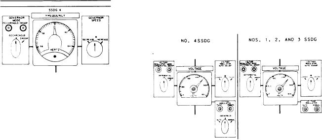
VOLTAGE REGULATOR MODE.--The
VOLTAGE REGULATOR MODE control indi-
Governor Control Section
cators and switch are located to the left of
This section has two switch/indicators for the
the VOLTAGE meter. The lights are labeled
governor mode and the governor speed. The
DIFFERENTIAL and DROOP. The indicator
GOVERNOR MODE switch/indicator controls
light that is illuminated indicates the mode of
the governor's mode of operation. The GOVER-
operation the voltage regulator is using. When the
NOR SPEED switch controls the speed of the
DIFFERENTIAL mode light is illuminated, the
SSDG.
generators maintain constant voltage through load
changes. When the DROOP mode light is
GOVERNOR MODE SWITCH.--The GOV-
illuminated, the voltage of the generator set
ERNOR MODE control switch and indicators are
varies indirectly with the load. Below the indicator
located to the left of the FREQUENCY meter.
lights is the VOLTAGE REGULATOR MODE
The lights are labeled ISOCHRONOUS and
selector switch with two positions, DIFFEREN-
DROOP. The indicator light that is illuminated
TIAL and DROOP. This switch is used to select
indicates the mode of operation the governor is
the voltage regulator's mode of operation.
using. In the ISOCHRONOUS mode, the
generators maintain constant speed through load
VOLTAGE REGULATOR AUTO ADJUST.--
changes. In the DROOP mode, the speed of the
The VOLTAGE REGULATOR AUTO ADJUST
generator set varies indirectly with the load. Below
switch is located to the right of the VOLTAGE
the indicator lights is the governor mode selector
meter. It is a three-position switch, spring
switch with two positions, ISOCHRONOUS and
loaded to the center position. When the switch
DROOP. It is used to select the governor's mode
is turned to the right or the RAISE position, it
of operation.
will cause the voltage of the generators to increase.
When the switch is turned to the left or the
GOVERNOR SPEED SWITCH.--The GOV-
LOWER position, it will cause the voltage of the
ERNOR SPEED switch is located to the right of
generators to decrease.
the FREQUENCY meter. It is a three-position
switch, spring loaded to the center position. When
VOLTAGE REGULATOR.--The VOLTAGE
the switch is turned to the right or the INCREASE
REGULATOR indicators are located below the
position, it will cause the frequency of the
VOLTAGE REGULATOR AUTO ADJUST
generator to increase. When it is turned to the left
switch. The two indicator lights are labeled AUTO
or the DECREASE position, it will cause the
and MANUAL. The No. 4 SSDG also has a three-
frequency of the generator to decrease.
position selector switch. This switch functions
the same as those in the same sections on the DD
consoles. The switch positions are labeled AUTO,
DEENERGIZE, and MANUAL. This switch is
used to control the type of voltage regulation.
Voltage Regulator Control Section
The voltage regulator control section has
three separate controls for the VOLTAGE
REGULATOR MODE, the VOLTAGE REGU-
LATOR AUTO ADJUST, and the VOLTAGE
REGULATOR. The voltage regulator mode
controls the voltage regulator's mode of operation.
8-36