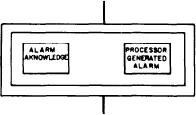
Alarm Acknowledge and Processor
meters, one of the bus ties, or shore power. The
Generated Alarm Section
middle meter is a CURRENT meter. The input
to this meter is controlled by the upper switch.
This section has two push-button switches,
This selector switch allows the operator to select
ALARM ACKNOWLEDGE and PROCESSOR
which bus tie is connected to the CURRENT
GENERATED ALARM.
meter.
When the ALARM ACKNOWLEDGE push-
button switch is depressed after an alarm has been
GROUND STATUS TEST Section
received, the audible alarm will be silenced and
the flashing alarm indicator will change to a steady
The GROUND STATUS TEST section has
light.
three indicator lights labeled PHASE, and from
The PROCESSOR GENERATED ALARM
left to right, A, B, and C. These indicators are
will occur when an out-of-tolerance condition
normally of equal brilliancy. To the right of
occurs on equipment being monitored; an alarm
the indicator lights is a rotary switch labeled
is generated in the EPCC by the fault alarm
SWITCHBOARD. This switch has four positions,
circuit. The status of the parameter is also checked
one for each SWBD. At the bottom of this
by the processor, a special-purpose computer,
section is a push-button switch labeled BUS
located in the EPCC. The processor compares the
GROUND TEST. When this switch is depressed,
signal with the alarm set value to determine if an
it connects the selected SWBD to the related
out-of-tolerance condition exists. If the condition
indicator lights for testing that SWBD for a
does exist, the processor checks the equipment
grounded condition. A ground will be indicated
fault alarm circuitry to determine if the fault
by one of the lights going out and the other two
lights glowing brighter. The light that goes out
alarm has been actuated. If the fault alarm has
is the phase that is grounded.
not been actuated but an alarm condition is
detected by the processor, the PROCESSOR
GENERATED ALARM indicator flashes and an
GENERATOR 4 Section
audible alarm sounds.
The GENERATOR 4 section has a rheostat
and is labeled VOLTAGE REGULATOR
MANUAL ADJUST. The rheostat is used to
adjust the voltage on the No. 4 SSDG when it is
in manual voltage regulation.
Audible Test Switches
and Rheostat Section
SYSTEM OUTPUT MONITOR/
The audible test switches and rheostat section
GROUND STATUS TEST/
is located at the bottom of the panel. It contains
two push-button switches and a rheostat. The
GENERATOR 4 PANEL (A-6)
push-button switches are for testing the horn and
The SYSTEM OUTPUT MONITOR/
bell. They are labeled HORN TEST and BELL
GROUND STATUS TEST/GENERATOR 4
TEST. The rheostat is for controlling the volume
panel (A-6) is the middle right panel (fig. 8-18).
of the audible tones.
It contains the system output monitor section,
The LAMP TEST push-button switch is
located at the bottom to the left of the test
ground status test section, generator 4, and
audible alarm test switches and rheostat.
swtiches. It is used to test the indicator lights on
the A-4, A-5, and A-6 panels only.
SYSTEM OUTPUT MONITOR Section
SSDG PANEL (A-7)
The SYSTEM OUTPUT MONITOR section
contains three meters (FREQUENCY, CURRENT,
The SSDG panel (A-7) is the bottom left panel
and VOLTAGE) and two selector switches. The
(fig. 8-19). It is subdivided into four columns. The
top meter and bottom meter inputs are controlled
columns are labeled PRIME MOVER (4, 2, 3, and
by the bottom selector switch. The selector switch
1). Each column is identical, one for each SSDG.
allows the operator to select which input is
We will describe a column from the top to the
applied to the FREQUENCY and VOLTAGE
bottom.
8-37

