COMPRESSOR CONSTRUCTION.--The
rotor and stators are enclosed in the compressor
case. Today's GTEs use a case that is horizontally
divided into upper and lower halves. The halves
are bolted together with fitted bolts and dowel
pins located at various points for casing align-
ment. This ensures proper casing half alignment.
Other assemblies can then be bolted to either end
of the compressor case.
On some older design engines, the case is a
one-piece cylinder open on both ends. The one-
piece compressor case is simpler to manufacture,
but any repair or detailed inspection of the
compressor rotor requires engine removal and
delivery to a shop. At the shop it is disassembled
for inspection or repair of the rotor or stator. On
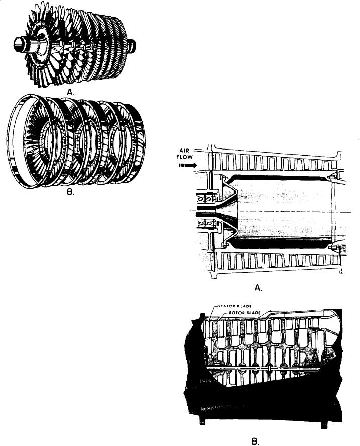
Figure 1-11.--Components of an axial-flow compressor.
A. Rotor. B. Stator.
take in ambient air and increase its velocity and
pressure. The air is then discharged through the
diffuser into the combustion chamber.
The two main elements of an axial-flow
compressor are the rotor and the stator (fig. 1-11).
The rotor has fixed blades which force the air
rearward much like an aircraft propeller. Behind
each rotor is a stator which directs the air
rearward to the next rotor. Each consecutive pair
of rotor and stator blades constitutes a pressure
stage.
The action of the rotor at each stage increases
compression and velocity of the air and directs
it rearward. By virtue of this increased velocity,
energy is transferred from the compressor to the
air in the form of velocity energy. The stators at
each stage act as diffusers, partially converting
this high velocity to pressure.
The number of stages required in a compressor
is determined by the amount of air and total
pressure rise required by the GTE. The greater
the number of stages, the higher the compression
ratio. Most present-day engines have 8 to 16
Figure 1-12.--Compressor rotors. A. Drum type. B. Disk
stages.
type.
1-12

