engines with the split case, either the upper or
The two main types of axial compressor rotors
lower case can be removed, allowing the engine
are the drum type and the disk type.
to remain in place for maintenance and
Drum Type.--The drum-type rotor (fig. 1-12,
inspection.
view A) consists of rings that are flanged to fit
The compressor case is usually made of
one against the other. The entire assembly may
aluminum or steel. The material used will depend
then be held together by through bolts (often
on the engine manufacturer, the weight require-
called tie bolts). The drum is one diameter over
ments of the engine, and the accessories attached
its full length. The blades and stators vary in
to the case. The compressor case may have
their radial length from the front to the rear
external connections made as part of the case.
of the assembly. The compressor case tapers
These connections are normally used as bleed air
accordingly. This type of construction is satisfac-
ports to aid in the prevention of stalls during
tory for low-speed compressors where centrifugal
starting and acceleration or at low-speed
stresses are low.
operation.
Disk Type.--The disk-type rotor (fig. 1-12,
view B) consists of a series of disks of increasing
diameter which are machined from forgings and
shrunk fit over a steel shaft. Another method of
rotor construction is to machine the disks and
shaft from a single aluminum forging and bolt
steel stub shafts on the front and rear of the
assembly. The stub shafts provide bearing
support surfaces and splines for joining the
turbine shaft. The blades decrease in length from
entry to discharge. This is due to a progressive
reduction in the annular working space (drum to
casing) toward the rear. The working space
decreases because the rotor disk diameter
increases. The disk-type rotors are used almost
exclusively in all present-day, high-speed engines.
COMPRESSOR BLADING.--Each stage of
an axial compressor has a set of rotor and stator
blades. Stator blades may also be referred to as
vanes. The construction of these blades is
important to efficient operation of a GTE.
Rotor Blades.--The rotor blades are usually
made of aluminum, titanium, or stainless or
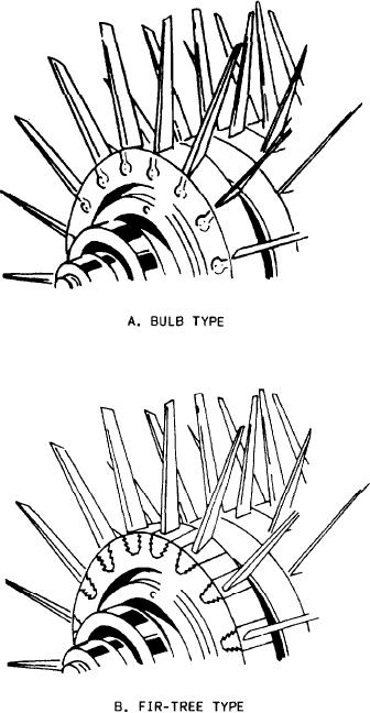
semistainless steel. Methods of attaching the
blades in the rotor disk rims vary. They are
commonly fitted into the disks by either the bulb
or the fir-tree type of roots (fig. 1-13, views A and
B). The blades are then locked with grub-screws,
lockwires, pins, or keys.
Compressor blade tips are reduced by cutouts,
which are referred to as blade profiles. Some
manufacturers use a ring (usually called a shroud)
that acts as a spacer for the stators. The shroud
can also act as a wear surface when the blade tips
come into contact with the ring. This rubbing of
blade tips maintains the close tolerances necessary
to maintain the efficiency of the compressor and
the profiles prevent serious damage to the blade
or housing.
Figure 1-13.--Rotor blades.
1-13

