
The turbine rotor has four wheels containing
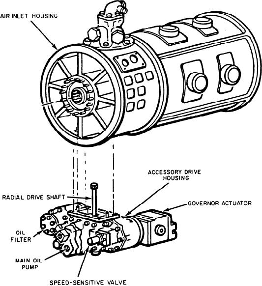
pump, governor actuator, and external scavenge
oil pump. Pads on the front face are for the speed-
the turbine blades and is supported at each end
sensitive valve, main oil pump, and oil filter (this
by roller bearings. The turbine rotor extracts
requires no gearing). The components themselves
energy from the hot exhaust gas. It converts this
are discussed later in this chapter. The accessory
energy into shaft horsepower to drive the com-
pressor through a coupling shaft that runs through
drive is driven by the compressor rotor extension
the combustion chamber inner casing liner as-
shaft. This is accomplished by bevel gears that
drive a radial drive shaft, located in the inlet hous-
sembly and the generator through the PTO shaft
ing. The radial drive shaft is splined into one bevel
and reduction gear. This is different from the
gear through the bottommost strut of the inlet
LM2500 GTE. It uses one turbine to drive its com-
housing. A pinion on the other end of the shaft
pressor and a separate turbine to drive its load.
drives the gears in the accessory drive housing.
ACCESSORY DRIVE SECTION
ENGINE SYSTEMS
The accessory drive housing (fig. 3-15) pro-
vides mounting pads on the front and rear faces.
As previously mentioned, the model 104 and
The pads on the rear face are for the fuel
the model 139 both use the same GTE. However,
Figure 3-15.--Allison 501-K17 accessory drive housing.
3-18