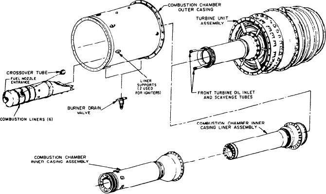
turbine inlet casing at the rear. The aft end of the
inner casing is bolted to the turbine inlet casing.
The front end is supported by a sleeve in the
The combustion section has six individual
diffuser.
combustion chambers (burner cans) (fig. 3-13).
About 25 percent of the compressor discharge
They are equally spaced in an annulus formed by
air entering the combustion section passes to the
a one-piece outer casing and a two-piece inner
burner cans. Combustion takes place in the six
casing. Six crossover tubes connect the burner
cans. These provide flame dispersal during
combustion liners. Air initially enters the liners
through vanes at the front of the liners that swirl
starting. The burner cans are held by the fuel
the airflow. The swirling air mixes with the fuel
nozzles, spark igniters (two chambers), and liner
sprayed into the liners by the fuel nozzles. The
supports (four chambers). The burner cans are of
mixture is ignited during start by the spark igniters
welded construction.
located in two of the liners (these are described
The outer casing encloses the burner cans and
later in this chapter). After a start, a steady flame
provides the supporting structure between the
is established by the constant addition of fuel and
diffuser and turbine. The casing has two drain
air.
valves to drain unburned fuel after shutdown or
Holes along the body of the liners allow
after a false start. They may be called either
cooling air to enter the liners. This air provides
burner drain valves (model 104) or combustor
a buffer between the liner and the hot flames. Two
drain valves (model 139). These valves open when
reverse flow baffles ensure the liners direct air
combustion pressure drops below 1 to 5 psig. They
from some of the cooling air holes toward the
close above 2 to 5 psig on increasing pressure.
front of each liner. This cools the forward portion
The two-piece inner casing has an inner casing
of the liners and provides additional turbulence
and inner casing liner. These are separated by an
(for better combustion) of the fuel and air
air space and bolted together at the front. The
mixture. The hot gases produced in the liners exist
inner casing liner has a bellows to take up thermal
through a transition section into the turbine.
expansion and contraction. It is bolted to the
Figure 3-13.--Allision 501-K17 combustion section.
3-16

