AIR INTAKE
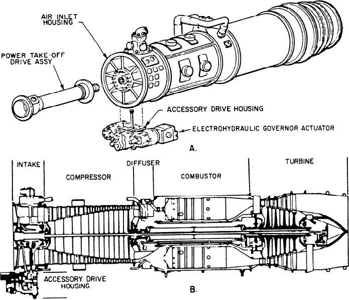
compressor (fig. 3-9). The GTE drives the
generator through a reduction gear. The reduction
The air intake has a one-piece cast aluminum
gear is mounted in front of the GTE. It is
inlet housing. This forms the airflow path to the
connected to the compressor front shaft by a
compressor. Figure 3-10 shows the air inlet
power take-off (PTO) shaft assembly. The GTE
housing, the compressor IGV assembly, and the
is mounted on a suspension system at its
compressor front frame assembly. The housing
approximate center of gravity. It is adjusted so
has an outer case, a center hub, and eight struts
minimum stress is placed on the bolted flanges
of the PTO housing. Engine to reduction gear
connecting the hub to the outer case. The hub
misalignment is, therefore, minimized when
contains the compressor front bearing. This
movement occurs because of shock or thermal
supports the forward end of the compressor rotor,
the bearing labyrinth seal, and the bevel gears.
growth changes. The direction of rotation of the
The bottom strut contains the radial drive shaft.
engine is counterclockwise when viewed from the
The shaft transfers power from the compressor
exhaust end.
rotor to the AGB, which is used to drive the
In this section we will describe the Allison
accessories. The outer case has a pad on the
501-K17 air intake system; the compressor,
bottom that provides the mounting for the AGB.
combustor, and turbine section; and the accessory
The turbine breather is mounted on the top. The
drive section.
Figure 3-9.--Allison 501-K17 GTE. A. Overall view. B. Cutaway view.
3-12

