
the engine is motoring. The nozzles are mounted
mounted in pairs above and below the air inlet
in the forward wall of the inlet plenum. Except
housing. Each pair has one primary and one
for the spray nozzles and the solenoid-operated
secondary discharge nozzle. The CO2 is piped to
signal air valve (not shown) located under the
the module from the primary and secondary CO2
module, all components of the water wash system
tank banks. When the flame detector detects a
are ship's systems.
fire, an electrical signal from the vent fan
controller activates the primary CO2 system. If
failure of the primary system occurs, or the
FIRE DETECTION AND
primary is not enough to extinguish the fire, the
EXTINGUISHING SYSTEMS
secondary system can be manually activated at the
Figure 3-5 also shows the fire detection and
module or outside the space.
extinguishing system. This system has two UV
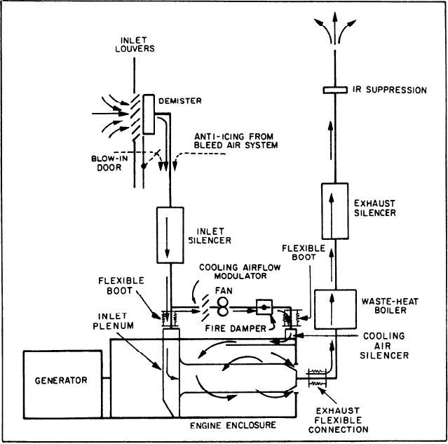
INTAKE, COOLING, AND EXHAUST
flame detectors, a signal conditioner (not shown),
SYSTEMS
and four CO2 discharge nozzles. The flame
detectors are mounted on the engine side of the
The intake, cooling, and exhaust systems (fig.
inlet plenum wall. The CO2 discharge nozzles are
3-6) provide the flow path for combustion and
Figure 3-6.--GTGS intake, cooling, and exhaust systems.
3-7