
must be released manually at the bank. The
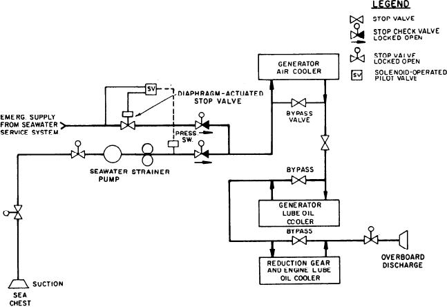
the three coolers. Therefore, each unit has a
bypass valve to adjust the amount of seawater
secondary system is not equipped with monitors
flowing through the cooler. This amount is
or alarms. Once released, CO2 discharge cannot
based on the temperature of the oil or air being
be stopped. The secondary discharge is at the rate
cooled.
of 67 lb/min.
If the electric pump system fails, emergency
cooling water is supplied by the ship's seawater
SEAWATER SERVICE SYSTEM
service system. This is accomplished by activation
of the pressure switch that senses pump discharge
Each GTGS has an independent seawater
pressure. If the GTGS is running and pump
service system for the lube oil coolers and
discharge pressure drops below the pressure switch
generator air cooler. Power for the pumps is taken
set point, the solenoid-operated pilot valve will
from the generator side of the main circuit
energize, opening the diaphragm-actuated stop
breaker. Thus, the electric pumps start automa-
valve and circulating the emergency seawater
tically as the generator's voltage exceeds excitation
supply through the coolers. Seawater is discharged
voltage. Figure 3-8 is a flow diagram of this service
system. A solenoid-operated pilot valve auto-
overboard through an emergency stop valve.
matically opens the diaphragm-actuated,
hydraulically operated stop valve when LP
GTE ASSEMBLY
contacts close in the pressure switch in the normal
service line. Cooling water is drawn from the sea
The Allison 501-K17 is a single-shaft, axial-
chest. It flows through a strainer and then the
f l o w GTE. It has a 14-stage axial-flow
generator air cooler and lube oil cooler. It passes
through the reduction gear/engine lube oil cooler.
compressor, a can-annular combustor, and a
4-stage axial-flow turbine directly coupled to the
The seawater flow requirements are different for
Figure 3-8.--Generator seawater service system.
3-11