If the temperature continues to rise, standby fan
200F. The RTD provides a continuous enclosure
B will start at 190F. It will continue to run until
temperature signal to both the LOCOP and
the temperature drops to 180F. When you secure
propulsion and auxiliary machinery information
the GTG, the lead fan will continue to run until
system equipment (PAMISE). The signal in the
the temperature drops to a point below 140F.
PAMISE is used for data logging and the demand
display indicators (DDIs). The thermostat controls
When the LOCOP switch is positioned on
MANUAL, you can select a fan by using the
the operation of the louvered cooling air
LOCOP push-button indicators. The fan selected
modulator.
will operate until it is stopped manually.
The RTD on the model 139 operates like the
CG CLASS MODULE TEMPERATURE
RTD on the model 104 except that the RTD in
MONITORING. --Two temperature switches, a
the enclosure provides a temperature signal to the
thermostat, a manual rotary selector switch, and
EPCC that activates the ENCLOSURE TEMP
an RTD are associated with the cooling air system.
HIGH alarm indicator at the EPCC.
The manual rotary selector switch is located on
the LOCOP. It is a four-position switch: FAN A,
WATER WASH SYSTEM
FAN B, MANUAL, and OFF. When the selector
switch is positioned on FAN A or FAN B, this
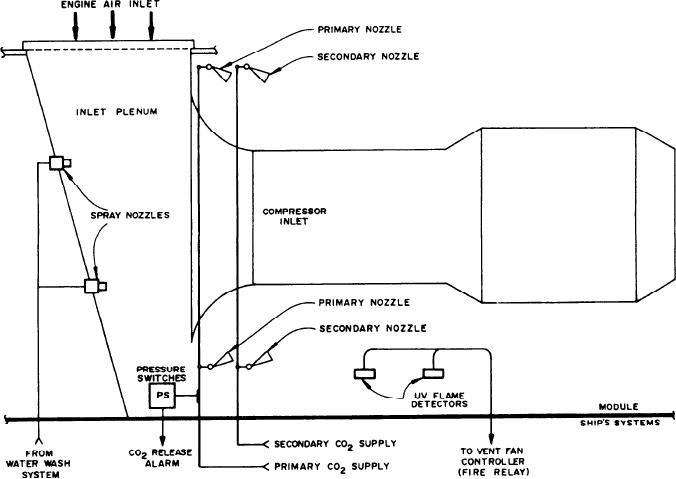
Figure 3-5 shows the components of the water
selects the lead fan. The temperature switches
wash system and the CO2 system. The CO2 system
work with the rotary switch to determine which
is discussed later in this chapter. The water wash
is the lead fan or for manual operation. With the
system is used to clean the compressor section of
rotary switch in the FAN A position, fan A will
the GTE. Two spray nozzles spray chemical
act as lead fan. When the GTG is started, fan A
cleaner or fresh water into the engine inlet while
will start at an enclosure temperature of 170F.
Figure 3-5.--GTGS water wash and CO2 systems.
3-6

