
supports the entire GTGS system except for these
these systems to the GTGS. These and other
services interface connections are made at the
voltage regulator unit (including the electronic
module (fig. 3-3).
governor) and an externally mounted oil cooler
for the GTE and the reduction gear lube oil
systems.
GAS TURBINE GENERATOR SET
MODULE COMPONENTS AND
ENCLOSURE
SYSTEMS
The module components and systems support
The engine and the reduction gear assembly
the operation of the engine, reduction gear, and
are housed in an acoustical enclosure (fig. 3-4).
generator. These components and systems include
The enclosure reduces the noise level within the
the base, the enclosure, the cooling air flow and
machinery space and ducts cooling air for the
temperature monitoring systems, the water wash
GTE. Barrier walls and the air inlet plenum within
system, the fire detection and extinguishing
the enclosure separate the engine compartment
system, the intake and exhaust systems, the GTGS
from the reduction gear compartment.
fire detection and CO2 system, and the seawater
service system.
Blow-In and Blow-Out Panels
BASE
Figure 3-4 shows the blow-in and blow-out
panels on the enclosure. They prevent damage to
The GTGS base is a steel frame attached to
the GTGS due to high or low external pressure.
the ship's structure through 5000-pound capacity,
The panels are spring-loaded in the closed
shock/vibration isolating mounts. Twelve mounts
position. The blow-in panel is located in the left
are used for the model 104 GTGS; fourteen are
wall of the enclosure. It is near the aft end and
used for the models 119 and 139 GTGSs. The base
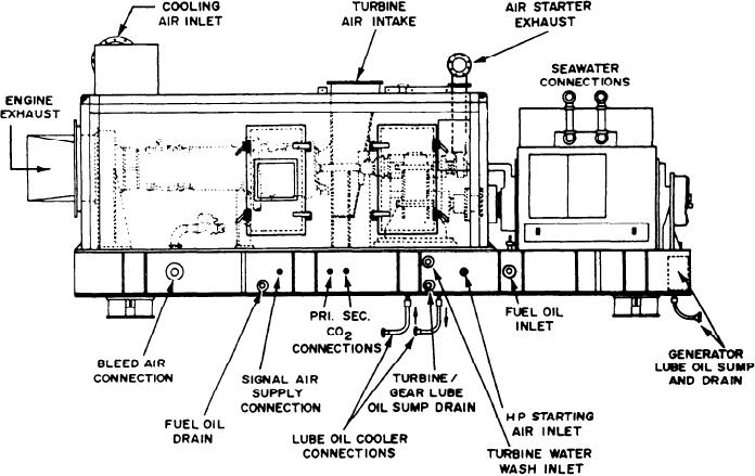
Figure 3-3.--GTGS ship's system interface connections.
3-4