
respectively, on the second platform level. They
The GTGSs can be started and monitored
are located opposite the main engines. The No.
locally at the LOCOP (4) mounted on the genera-
3 GTGS is located in the No. 3 generator room
tor housing or remotely from the SWBD or EPCC
at the first platform level. This arrangement
in CCS. The LOCOP contains the electronic con-
separates each GTGS by at least three watertight
trols that sequence and monitor the operation of
bulkheads. This reduces the change of total loss
the GTE. Control of generator voltage, fre-
of electric power because of battle damage. Figure
quency, and the generator circuit breaker is
3-1 shows the equipment layout of a GTGS. Refer
available at either the EPCC or the SWBD.
to the numbers listed in parentheses after each
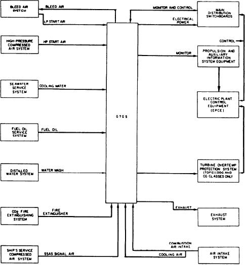
Each GTGS has its own seawater cooling
description to locate the component in figure
system and lube oil system (5). The module is
3-1.
cooled by air supplied from the intake system
Each GTGS is a module consisting of a GTE,
through an electric fan. Two fans are used on the
a reduction gear assembly, and a generator. These
CG classes. The module receives
are all mounted on a common base with asso-
starting air from the bleed (low-pressure) (6) and
ciated engine controls and monitoring devices.
high-pressure (7) air systems, signal air from the
Each GTGS is about 25 feet long, 7 feet wide, and
ship's service air system (SSAS), cooling and
9 feet high. The GTE and reduction gear assembly
emergency cooling water from the seawater service
are housed in an acoustical enclosure (1). Each
system, fuel from the engine room's fuel oil (FO)
generator has a remotely mounted generator
service system, carbon dioxide (CO2) from the
control unit (2). The lube oil cooler (3) for each
fire extinguishing system, and gas turbine
gas turbine/reduction gear system is mounted
cleaning/rinsing solution from the water wash
under the module base.
system. Figure 3-2 shows the interrelations of
Figure 3-2.--GTGS interrelation with ship's systems.
3-3