
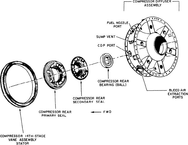
Figure 3-12.--Allison 501-K17 diffuser and 14th-stage stator vane assembly.
housing also has passages for directing anti-
guide vanes. The rotor is made up of 14 individual
icing air to the strut leading edges and the
wheels. The wheels contain the 14 stages of blades
IGV assembly. This assembly is located in
and are pressed and bolted together as one
the after side of the inlet housing. However,
assembly.
in this application, engine anti-icing is no longer
used.
The diffuser is of welded steel construction.
It is used to slow the compressor discharge air
before entering the combustor. The diffuser
COMPRESSOR SECTION
supports the compressor rear bearing/thrust
bearing, the compressor seal (two-stage)
The compressor section has a compressor
stationary members, and six fuel nozzles. It
stator (fig. 3-11, view A), a compressor rotor (fig.
provides three bleed air extraction ports to which
3-11, view B), and a diffuser (fig. 3-12). The air
a manifold is attached. This allows bleed air
inlet housing described in the preceding paragraph
extraction (up to 10 percent of total engine
is also part of the compressor section. The
airflow) to the ship's bleed air system. Bleed air
compressor case is made up of four sections bolted
is also extracted for use in keeping the 5th- and
togetber along horizontal split lines. The case
10th-stage bleed valves closed during normal
operation.
contains the 14 stages of stator vanes and the exit
3-15