Home
Download PDF
Order CD-ROM
Order in Print
Figure 3-9.--Allison 501-K17 GTE. A. Overall view. B. Cutaway view.
Figure 3-11.--Allison 501-K17 compressor. A. Stator. B. Rotor.
Gas Turbine Systems Technician (Electrical/Mechanical) 3, Volume 2
Page Navigation
103
104
105
106
107
108
109
110
111
112
113
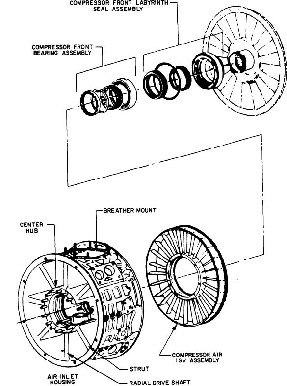
Figure
3-10.--Air
inlet
housing,
IGV
assembly,
and
compressor
front
frame
assembly.
3-13