after cleaning. Each filter chamber has a vent and
Lube Oil Filter
a drain.
The LO filter has two separate filter housings
The liftout filter elements are pleated wire
cloth, supported by inner and outer perforated
connected by interlocked inlet and outlet valves
metal tubes. Magnets, supported inside each filter
arranged so only one housing is in operation at
element, remove ferrous particles from the oil.
a time. Each filter housing contains 14 filter
elements rated at 65 microns. You can clean and
Header
reuse the filter elements. Each filter housing has
vent and drain connections. The filter is installed
Oil is supplied to the MRG and accessories by
in the piping downstream from the LO cooler to
the ship's main LO service system through a single
remove particulate matter from the LO. The filter
oil inlet LO header. The header has spray bar
has a single cast steel body mounted on a
assemblies equipped with spray nozzles to
fabricated steel base. The filter body contains two
lubricate all gear and pinion teeth. The spray
filter chambers and a diverting valve assembly.
nozzles are arranged to direct oil across the full.
The diverting valve connects the filter chambers
width of the teeth at the gear mesh. This properly
to the inlet and outlet ports. The filter chambers
lubricates tooth bearing surfaces and dissipates
are covered by bolted steel plates.
heat generated during operation.
A manually operated changeover assembly
Safety orifice plates are used for journal and
positions the diverting valve to place the right or
thrust bearings. The openings are sized to allow
left filter element in service. The selector lever is
sufficient lubrication under normal conditions but
positioned over the chamber selected. A hydraulic
to restrict excessive flow, such as that caused by
interlock prevents the shifting of oil flow to an
extreme bearing wear or bearing failure. These
open (nonpressurized) filter chamber. An inter-
orifice plates are installed in the flange joints
lock cylinder is connected to each of the filter
connecting the oil supply line to each bearing.
chambers. When a differential pressure exists
Orifice plugs are installed in the bearing seats for
between the chambers, the cylinders engage a
the high-speed pinions and input shafts.
notch in the diverting valve cam plate and
positively lock the selector lever. The changeover
SYSTEM MONITORING
assembly has a balancing valve that is used to
During operation, another one of your duties
equalize pressure between the chambers to allow
as watch stander is to monitor the LO system.
shifting. The assembly also fills the filter chamber
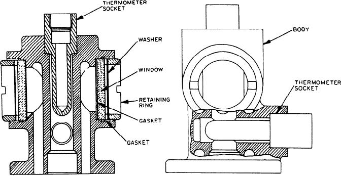
Figure 4-2.--Liquid sight indicator.
4-10

