tanks. The FO in the service tanks can also be
recirculated through the purifier and back to the
service tanks by realigning the valves. The FO
must be circulated for a minimum of 3 hours
before a service tank is placed in operation. This
provides a means of continuously reducing the
amount of solid contaminants in the FO.
The CG-, and DD-class ships are
being furnished with self-cleaning centrifugal
purifiers (SCCPs). The purifier is a vertical, direct-
drive, centrifugal, self-cleaning (solids ejecting)
machine that has the capacity to purify 110 gpm
of contaminated diesel fuel, marine. The FO
contaminated with water and solids is fed into the
purifier. It separates the pure FO from the
contaminants and returns the purified FO to the
ship's FO system. The water is continuously
passed from the purifier through the ship's
piping to a waste oil tank. Separated solids in the
form of sludge are retained within the bowl
during the cycle. Cleaning the bowl during purifier
operation is referred to as "shooting" the bowl.
The ejected sludge is also passed to the waste oil
system. The purifier can remove water from a
contaminated mixture comprised of as much as
half water, half FO. Also, under emergency
conditions, the purifier can process 100% water for
a period of 5 minutes without any water discharge
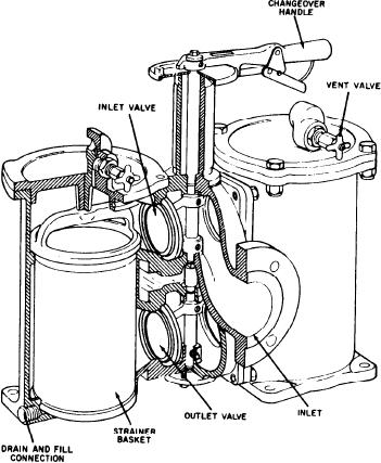
Figure 4-7.--Duplex FO strainer.
from the fuel discharge port.
Fuel Oil Service System
through the outlet. Duplex strainers contain two
separate strainer housings and baskets and a
The FO service tanks are similar to storage
changeover mechanism that is a shaft with inlet
tanks except they are not saltwater ballasted. The
and outlet valves attached to it. As the handle is
FO service tanks have the same type of liquid-level
moved, one set of valves opens and the other set
indicating system as other tanks aboard ship. The
closes, isolating one strainer assembly. The
major concern for the service tanks is cleanliness.
strainers have differential pressure gauges and
The FO service tanks must be maintained in a
alarm indicators to alert the operator when the
clean state of readiness. To maintain cleanliness,
strainer is dirty.
you must allow only clean FO to enter the
service tanks. The components of this system that
FUEL OIL BOOSTER PUMPS.--Each FO
we will discuss are the FO strainers, the FO heater,
service system has two booster pumps to provide
and the filter/coalescer.
the system pressure. The FO booster pump is a
vertical, screw-type, positive-displacement pump
FUEL OIL STRAINERS.--A wire-mesh
that is driven by a two-speed electric motor. This
basket strainer is normally installed between the
type of pump is found on the CG-, and DD-
service tank and the booster pump suction to filter
class ships. A sliding vane pump is used on
out large solid particles. Figure 4-7 is an example
the FFG-class ships. Directly following the pump
of a duplex FO strainer. Refer to volume 1,
discharge is a relief valve. Since the pump is
chapter 6, of NAVEDTRA 10563 for more
positive displacement, a relief valve is required to
detailed information on this type of strainer.
protect the system and the pump. The relief valve
The FO enters the top section of the strainer
bypasses FO back to the pump inlet.
body and is directed into one of the wire-mesh
baskets. Large, solid particles are trapped inside
FUEL OIL HEATER.--Fuel oil heaters are
the strainer basket, and clean FO travels on
installed in the service system after the FO booster
4-15

