
is composed of a rod or series of rods mounted
indicate FO levels in the tanks, indications of valve
vertically within the tank. The magnetic float is
alignment, alarms for high and low tank levels,
cylindrically shaped and has a hole in the center.
and, in the seawater-compensated system, an
As it moves up and down on the surface of the
alarm for receiving tank overpressurization.
fluid, the magnetic float operates tap switches
in the rod. The electrical resistance of the
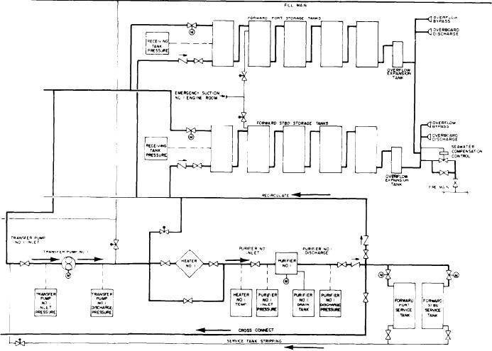
TRANSFER SYSTEM.--The FO transfer
transmitter changes according to which rod
system transfers FO from the storage tanks to the
service tanks. In the transfer process, the FO is
switches are closed. This provides an indication
cleaned for use in the GTEs. The system has
of tank level. The float movement is transmitted
to a receiver that is calibrated in gallons.
transfer pumps, heaters, and centrifugal purifiers.
Magnetic-float, liquid-level indicators in tanks
Figure 4-6 is a basic diagram of the FO
that overflow directly overboard have integral,
transfer system for the DD-class ship. It should
high-level alarms to warn of an impending over-
give you a good idea of how the system works.
board oil discharge. These alarms are set to sound
The oil king's first step is to decide from which
when the tank has reached 95 percent of total
storage bank FO is to be taken and to which
capacity. This alarm warns that the tank will
service tank it is to go. The FO is moved from
overfill and that oil will be discharged overboard
the storage tank by the transfer pump through the
FO transfer heater. The heater warms the FO to
unless the operator takes preventive action(s). On
the proper temperature for cleaning by the
most gas turbine ships, the FO system is
purifier. The FO purifier removes water and
monitored from a central point on the ship. A
contaminants as FO is transferred to the service
system control panel has gauges and alarms that
Figure 4-6.--DD-class ship fuel oil system.
4-14