
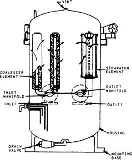
their own weight into the sump. The flow through
pumps. The heaters are heat exchangers of the
the separator elements is from the outside to the
conventional shell and U-tube type. Either steam
inside. The FO, free of contaminants, then flows
or hot waste water is used with a temperature-
out of the coalescer through the discharge valve
regulating valve to maintain the FO at normal
into the FO system.
operating temperatures. An alarm in the system
When the water/sediment level in the sump
indicates high FO temperature to the plant
operator.
reaches a preset level, the automatic drain valve
dumps into the water/sediment waste oil system.
A sampling valve is provided at the discharge
FILTER/COALESCER. --The filter/coalescer
point for testing discharged FO.
(also called the coalescer) is the last conditioning
As you can see, both the compensated and
station before the FO is used in the GTEs. The
noncompensated FO systems are basically the
coalescer filters sand, dust, dirt, and scale from
same in their operation. However, the quality of
the FO. The coalescer also coalesces water
the FO must meet stringent requirements. These
particles and removes essentially all free water
requirements help to protect the GTEs from
from the FO supplied to the propulsion gas
turbines.
serious damage, such as corrosion of the hot
section, fouling of engine controls, and plugging
The coalescer (fig. 4-8) is a self-contained,
of fuel nozzles. This level of FO quality is achieved
static, two-stage unit that combines the process
through the continuous purification, sampling,
of filtration and water separation in one housing.
and testing of FO throughout the system. This is
The basic principle of operation is that con-
the responsibility of the oil king on board the ship.
taminated FO enters the unit through the inlet
port and flows into and through the coalescing
JP-5 SYSTEM
elements. The flow through the coalescer elements
The JP-5 system provides FO to the helicopter
is from the inside to the outside. The coalescer
fueling station and to the small boat refueling
elements remove solid contaminants from the FO.
station. It also transfers JP-5 to the ship's FO
As FO passes through the elements, entrained
service system under emergency conditions to
water coalesces into large droplets that fall
operate the main engines and generators. On
to the bottom of the coalescer (sump) where they
the CG-, and DD-class ships, JP-5 can be
accumulate.
introduced into the system through the system
After passing through the coalescer elements,
piping just before it enters the FO booster pumps.
the FO passes through the hydrophobic screen and
On the FFG-class ships, JP-5 is normally provided
the separator elements, which remove the final
to emergency head tanks, which provide enough
traces of coalesced water that have not fallen by
FO for the normal cool down period (5 minutes)
of a main engine.
The JP-5 system is basically similar to the
ship's FO and transfer system in that it has
refueling stations, storage tanks, transfer pumps,
service tanks, and filter separators that provide
clean FO to the equipment. Onboard FO capacity
for JP-5 is much less than for fuel, naval distillate.
JP-5 is taken on board from topside fueling
stations and transferred to the storage tanks. The
storage tanks are noncompensated tanks and have
the same type of tank level indicators as the fuel,
naval distillate tanks. The FO is transferred from
the storage tanks to the service tanks through the
JP-5 transfer pump and filter separator. The filter
separator removes water and contaminants from
the FO before it reaches the service tanks. The
transfer piping system also branches off before
it reaches the service tanks. This provides JP-5
for emergency use in the ship's FO system and
also to the small boat refueling station.
The FO from the service tanks is used for
helicopter (helo) refueling and has its own JP-5
Figure 4-8.--Filter/coalescer assembly.
4-16