
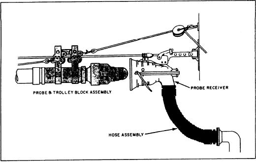
Figure 4-3.--Probe fueling system.
the FO enters the main header and from there to
(fig. 4-3) is used. The probe method is the most
the FO banks through branch lines. Each FO bank
common method used and is standard among
has its own motor-operated valve. These valves
ships of the U.S. Navy. Various adapters are
are operated from the fuel console and are either
available for fueling from ships not equipped
fully opened or fully closed.
with the probe unit. Part of this system is the
probe receiver and the hose assembly. They are
The storage tank valves on the CG-, and DD-
connected to deck filling connections on the
class ships are electrically operated from the
outboard side of the receiving ship. During inport
fuel control console located in CCS. Except for
refueling, the supplying activity's hose is bolted
the manual operation of the valves at the fueling
to a flanged fitting on board the receiving ship's
station, the entire fueling operation can be
fueling station.
conducted and monitored at the fuel control
With the commanding officer's approval, the
console. These valves can be opened and closed
chief engineer along with the oil king sets up and
manually if needed. A diagram of the FO fill and
controls the fueling operation. The oil king aligns
transfer header piping on the DD-class ship is
the system as specified in the EOSS and controls
shown in figure 4-4.
the fueling operation. Standard refueling stations
are manned and the entire operation is monitored
STORAGE TANKS.--The FO storage tanks
from a central point on the ship. Various tests of
are nothing more than large enclosed compart-
the FO are required before, during, and at the
ments with piping connected to them.
securing of fueling. The oil king is responsible for
The CG-, and DD-class ships are
these tests and also the reports that must be
provided with seawater-compensating systems. In
submitted.
this system, the storage tanks are always kept
The FO flows from the receiving station to the
completely filled with either FO or seawater
main header pipe and from there to the storage
ballast or a combination of both. The receiving
tanks through various valves. The valves are set
tank is connected to a bank of storage tanks by
up in a manifold system on the FFG-class ships
sluice piping between tanks. As a receiving tank
and are located in auxiliary machinery room No.
becomes full, FO overflows into the adjoining
1 (AMR1). On the CG-, and DD-class
tank in the bank. This continues until all tanks
ships, FO flows from the deck riser through a
in the bank are full. During the fueling operation,
motor-operated valve that can be used as a
seawater in the tank bank is displaced by the FO
throttling valve to maintain FO flow. From there
4-12