
air flow. The ambient air temperature sensor
After the bleed air passes the anti-icing, air-
signal determines the magnitude of valve position
flow regulator valves, it becomes anti-icing air and
change that will accompany any given engine
is piped to the GTGS intakes. Anti-icing air
speed change. Following an engine speed change,
entry into a GTGS intake is made through an
the controller will again regulate the temperature
8-inch pipe. The hot anti-icing air flows into the
of the inlet air in the intake to 38F. It does this
intake duct and mixes with the intake air. No
by comparing the bulk air temperature to the
manifolds or nozzles are used.
controller's 38F fixed temperature reference.
Injection of hot anti-icing air into the GTE
The controller used to operate the anti-icing
intakes is accomplished through the U-shaped
valve for each GTGS intake combines and
manifolds mounted at the 02 level above the
compares one input signal (duct air temperature)
silencers inside each duct. The manifolds are
with the fixed temperature signals (38F) to
constructed from 8-inch diameter pipe with
produce a torque motor control position signal.
1 1/4-inch holes drilled along the sides of each
The anti-icing valve used on a GTGS is the same
leg. Because of the larger cross-sectional area and
as that used on a GTM.
capacity of the propulsion intakes, manifolds
When the GTGS anti-icing temperature
must be used to mix the air thoroughly.
controller is enabled, it maintains the temperature
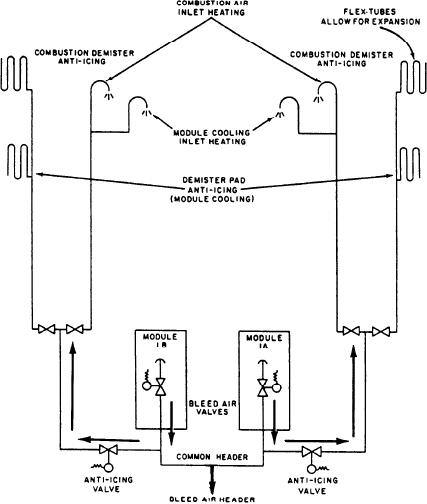
FFG Anti-Icing System
of the inlet air in the intake at 38F. Again the
controller compares duct air temperature to the
In the FFG anti-icing air system (fig. 4-10),
38F fixed temperature.
bleed air is taken from the common header and
Figure 4-10.--FFG anti-icing system.
4-19