
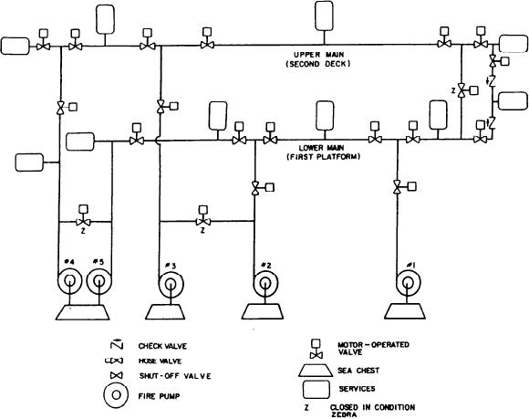
A simplified schematic of a firemain is
from the firemain system through interlocking
shown in figure 4-12. This schematic shows
this system as having five pumps feeding
two firemains, one on the port and the other
on the starboard side. The port is also referred
FIREMAIN SYSTEM
to as the upper main and the starboard as
the lower main. These mains can be cross-
The firemain system (also called fire and
connected or isolated by opening or closing the
flushing system) is a dual-purpose system. It
valves designated Z.
combines the services normally provided by the
auxiliary seawater cooling system besides the
normal services provided by the fire and flushing
system. This system provides the following types
SEAWATER SERVICE SYSTEM
of service:
The seawater service system is the ship's
1. Fire fighting
principal cooling water system. This system
distributes seawater throughout the engineering
3. Sanitary and waste disposal
plant at prescribed pressures and flow rates for
cooling LO, compressed air, and auxiliary
5. Electronics cooling
machinery. Although the different ship classes
6. Auxiliary machinery cooling
provide the same basic services, they are set up
7. Weapons cooling
differently. Therefore, we will describe them
8. Sprinkling system
individually.
9. Flushing
Figure 4-12.--Firemain diagram.
4-24