
status, time, logger commands, power supply
status, and selected parameter values.
AUTO SHUTDOWN STATUS SECTION.--
The auto shutdown status indicators (A) are LEDs
which illuminate red when an auto shutdown
occurs, either on GTE 1A or 1B. An auto shut-
down may occur because of vibration, low LO
pressure, or high T5.4. These indicators are
extinguished by depressing and holding the
AUTOMATIC SHUTDOWN push button on the
GTE 1B/1A panel.
TIME SECTION.--The time section (B) has
an LED digital display of the time in hours,
minutes, and seconds generated by the PCC real-
time clock.
LOGGERS SECTION.--The loggers section
(C) has two sets of thumbwheels and two push-
button switches. The thumbwheels are used to set
the month and day into the processor for use on
the automatic logger. These must be updated
daily. The push buttons are momentary-contact
types labeled DATA LOGGER PRINT and
BELL LOGGER PRINT. When either push
button is depressed, it will cause the data or bell
logger to print.
POWER SECTION.--The power section is
divided into two subsections, the PCC (D) and
the LOP (E). These two subsections provide
power supply status for the logic power supplies
in the PCC and LOP. They also provide console
115-volt ac status for the PCC. These indicators
are split-type and both halves are normally
illuminated. If either half of an indicator is
dark, perform a lamp test. If the lamp test
is satisfactory, check the indicated power supplies
for malfunctions.
PARAMETERS SECTION.--The parameters
section (F) has three digital display subsections
that the operator can use to monitor multiple,
selected parameters. Each subsection contains a
display, a thumbwheel, and a toggle switch. The
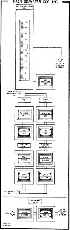
Figure 6-6.--Main seawater cooling panel.
thumbwheel is used to select an address, found
on a DDI listing, that calls up the selected
parameter. The parameter is displayed with the
three toggle switches. It allows the operator to
decimal in the proper position and with the units
verify the high/low reset value of the parameter
used to measure the parameter. The toggle switch
displayed.
is used to display either the high-alarm limit, the
MAIN SEAWATER COOLING Panel
actual value, or the low-alarm limit. Another
The MAIN SEAWATER COOLING panel
toggle switch, located on the lower left side of the
(fig. 6-6) is located on the left side of the middle
parameters section, is used with either of the other
6-8