
This sequence may only be initiated if the GTE
LOP. It contains the controls, indicators, and
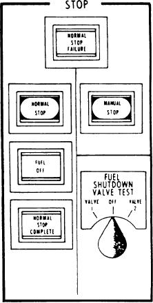
is at idle. By advancing the throttle above idle,
meters needed to operate the GTE. The GTE 1A
you can interrupt the normal shutdown any time
and GTE 1B panels are mirror images of each
before the fuel valve closure.
other. We will describe the independent push
buttons, indicators, and sections of the GTE 1B
The indicator labeled FUEL OFF is illuminated
panel in our discussion; keep in mind that the 1A
any time fuel manifold pressure is below 50 psig.
panel has identical features.
The indicator labeled NORMAL STOP COM-
PLETE, when illuminated, indicates T5.4 is
BATTLE OVERRIDE.--BATTLE OVER-
below 400F and fuel manifold pressure is
RIDE (A) is a guarded, illuminated, push button.
less than 50 psig within 90 seconds after the
You can use it at the PCC only if the PCC is the
completion of the 5-minute cooldown timer.
station in control. This switch will illuminate when
The other push button in this section is labeled
activated and overrides the following shutdowns:
MANUAL STOP. When it is depressed, the fuel
shutdown valves are de-energized, causing the
1.
Low GTE LO pressure
GTE to stop. This stop should only be done after
2.
High GTE vibration
the GTE has been allowed to cool down for
3.
High T5.4
5 minutes to prevent GTE damage.
4.
PLA failure for
The three-position switch located below the
a. PCS command signal out of limits,
MANUAL STOP push button is labeled FUEL
b. PT shaft torque out of limits, and
SHUTDOWN VALVE TEST. This switch is
c. PT speed out of limits.
spring-loaded to the OFF position. Moving the
switch to either the valve 1 or valve 2 position
BATTLE OVERRIDE will not override a flame-
will shut the corresponding fuel shutdown valve
out or a PT overspeed trip.
and should stop the GTE if the valve is operating
properly. This switch is used during PMS to
TORQUE LIMITING IN EFFECT.--The
test the integrity of each of the fuel shutdown
TORQUE LIMITING IN EFFECT indicator (B)
valves.
illuminates any time the torque limiting circuit is
restricting the movement of the PLA. This is done
until the torque on the GTE is within safe limits.
Then the torque limiting circuit will allow the PLA
to advance to the command position, provided
the PLA doesn't send the GTE into an over-
torque condition. If it does, then the torque
limiting circuit will take over as before. This will
continue until the command is obtained, or the
command is reduced to a lower setting.
STOP SECTION.--The STOP SECTION (C)
is located above the LO section on the engine
panel. The controls on the stop section are used
to perform normal and manual stops. This
section has three indicators, two push buttons,
and a switch used for GTE stopping.
The first indicator is labeled NORMAL STOP
FAILURE. This indicator illuminates if 90
seconds after the completion of the 5-minute
cooldown timer, T5.4 is above 400F or fuel
manifold pressure is above 50 psig. The first
control is a push button labeled NORMAL
STOP. It is used to initiate a stop using the
start/stop sequencer in the FSEE. This sequence,
upon initiation, allows the GTE to run at idle for
5 minutes. After 5 minutes, it de-energizes the fuel
shutdown valves, causing the GTE to shut down.
6-10