
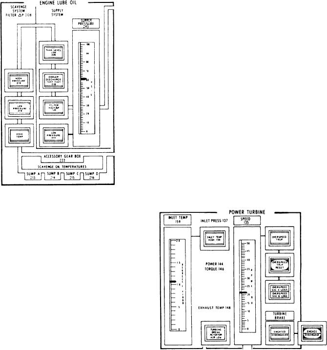
in either speed circuit occurs. When the PT speed
(Remember, an auto shutdown will occur if LO
becomes less than the loss-of-signal setting on
pressure drops to 6 psig.)
both speed signal input channels or greater than
the overspeed setting on either speed signal input
channel, the fuel shutdown valves de-energize (the
GTE will shut down). If the PT speed loss signal
occurs on only one channel, the GTE will
continue to run.
The bottom part of this section has a legend
above it labeled TURBINE BRAKE and is used
to control and monitor the operation of
the turbine brake. The TURBINE BRAKE
ACTUATOR AIR LOW indicator, located at the
bottom between the meters, will display when the
air pressure to the brake actuator is too low. It
illuminates when brake air pressure is less than
70 psig. The turbine brake indicator is a split-
legend indicator that displays the actual status of
the brake, either ENGAGED or DISENGAGED.
The momentary-contact push button/indicator
next to it is used to control the brake. This
push button will illuminate to show the operator
command to the brake. Depressing it will either
ENGAGE or DISENGAGE the brake assembly.
The turbine brake will not engage unless the PT
speed is below 250 rpm.
POWER TURBINE SECTION.--The PT
section (I) monitors the operation of the PT. It
has two meters, two push buttons, and five
indicators.
The first meter is the INLET TEMP (T5.4)
meter. It displays the temperature of the gas
entering the PT. Associated with this meter is the
INLET TEMP HIGH alarm indicator for high
T5.4. It has an alarm set point of 1500F. An
automatic shutdown will occur if T5.4 reaches
1530F and battle override is not on.
The second meter, the PT SPEED meter,
shows the speed of the PT. The meter is fed from
two sensors mounted on the rear frame of the
turbines that sense PT speed.
To the right of this meter is an OVERSPEED
TRIP indicator. It illuminates if either of the
sensors senses a PT speed greater than 3960 40
rpm. This causes the GTE to shut down because
ENGINE FUEL SUPPLY SECTION.--The
the fuel shutdown valves are de-energized.
ENGINE FUEL SUPPLY section (J) has the
Directly below the OVERSPEED TRIP
control and monitor components used to operate
indicator is the OVERSPEED TRIP RESET push
the fuel supply to the GTE.
button. It is used to reset the overspeed trip and
Starting at the top, which is labeled EMER-
to latch the fuel valves during manual starts.
GENCY FUEL SUPPLY, is a split-legend indica-
Below the OVERSPEED TRIP RESET push
tor labeled VALVE OPEN/VALVE CLOSED.
button is a split-legend indicator. It is labeled
It monitors the actual valve status of the
OVERSPEED SIG A LOSS/OVERSPEED SIG
emergency JP-5 supply valve. This valve's
B LOSS. These indicators will illuminate when the
normal position is closed. It is held closed
PT speed drops below 100 rpm or a malfunction
6-14