
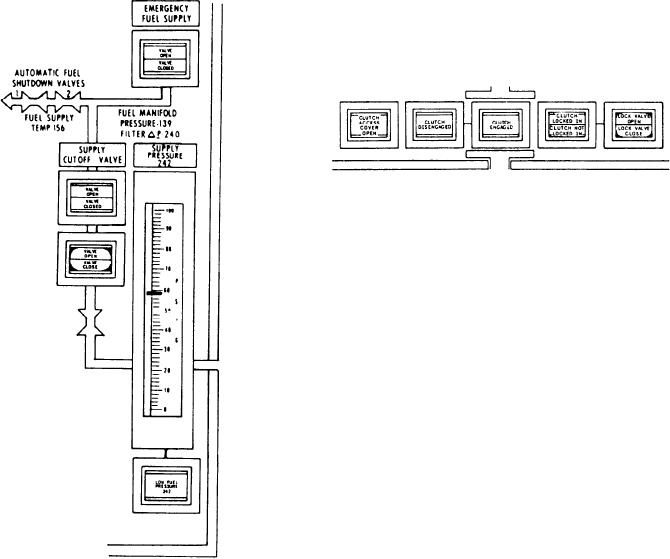
electrically. Upon loss of power the emergency
CLUTCH SECTION.--The clutches on the
JP-5 valve will open. This allows the GTEs to run
FFG-class ship are synchronized self-shifting. The
on JP-5 from a 350-gallon head tank.
only operator action required to engage and
Under the emergency fuel supply indicator
disengage them is the removal of the brake and
is a meter labeled SUPPLY PRESSURE. It
operation of the throttle.
displays the pressure of the fuel from the
fuel service system to the GTE. Under this
The CLUTCH section (K) of the panel has
meter and associated with it is the LOW FUEL
four indicators and one push button. The first
PRESSURE alarm indicator. It illuminates
indicator is labeled CLUTCH ACCESS COVER
and sounds an alarm at 8 psig. Fuel supply
OPEN. This indicator illuminates if the access
pressure is sensed after the fuel supply cutoff
door to the clutch is open. The next two indicators
valve.
display the clutch status and are labeled CLUTCH
The PCC has an indicator and control for the
DISENGAGED and CLUTCH ENGAGED. The
FUEL SUPPLY CUTOFF VALVE. The split-
fourth indicator is a split-legend indicator
legend indicator is labeled VALVE OPEN/
labeled CLUTCH LOCKED IN/CLUTCH NOT
VALVE CLOSED. It illuminates to indicate the
LOCKED IN. This indicator displays the status
actual position of the valve, either open or closed.
of the lock-in/lock-out mechanism of the clutch.
The split-legend, push-button control is labeled
Locking out the clutch provides for operation of
VALVE OPEN/VALVE CLOSE. It illuminates
the GTE without turning the MRG. For normal
to indicate the operator's command, either open
operation the clutch must be locked in. The last
or closed.
indicator is a split-legend, push-button control
labeled LOCK VALVE OPEN/LOCK VALVE
CLOSE. This indicator was a design feature
originally installed, but never used. It performs
no function.
Fuel Oil Service System Panel
Located between the two engine panels is the
fuel oil service system panel (fig. 6-8). The panel
is divided into two identical sections labeled FUEL
SYSTEM 2 and 1. Each section has controls and
indicators used to operate the fuel system on
either No. 1 or No. 2 tank, pump, heater,
prefilter, or filter/separator. The system can be
cross-connected to allow one tank and pump
combination to supply either or both GTEs.
An operator can monitor the FO service tank
by using the split-legend alarm indicator (A) at
the top of the panel labeled HIGH/LOW. It alerts
the operator when a tank is either full or needs
refilling. The meter (B) labeled TANK LEVEL
(1 or 2) indicates the actual level (in gallons) of
the tank. The FO tank suction and return valve's
split-legend indicator (C) labeled OPEN/CLOSED
6-15