
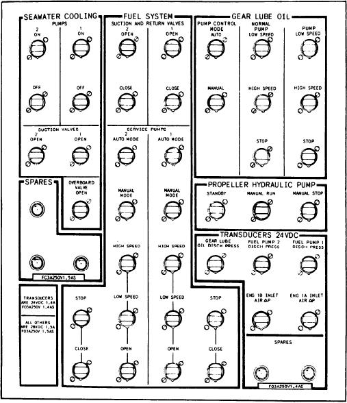
Figure 6-2.--PCC fuse panel.
a fuse panel (left side) and a status and fuse panel
shown on the figures. Refer to these letters to find
(right side). In the center of the top section of the
the section of a panel when it is discussed.
PCC is the demands panel. On either side of the
demands panel are the engine start panels (1A on
the right side, 1B on the left side). On the middle
Fuse and Status Panels
section of the PCC from left to right are the
seawater cooling panel, the engine 1B panel, the
The fuse panel (fig. 6-2) is located to the left
FO service system panel, the engine 1A panel, and
of engine start panel 1B. This panel has seven
the reduction gear LO panel. The lower section
sections of fuses, two of which contain spare fuses
of the PCC is the propulsion control panel. This
for the panel. The other sections are labeled
panel has the throttle controls, the propeller pitch
SEAWATER COOLING, FUEL SYSTEM, GEAR
hydraulic oil panel, and an MRG bearing mimic
LUBE OIL, PROPELLER HYDRAULIC PUMP,
display.
and TRANSDUCERS--24 VDC. When a gener-
ated command is not received, troubleshooters
Follow the related figures as we discuss the
should begin by checking the associated fuses. The
various PCC control and indicating panels. The
only time voltage is applied across the fuse is when
parenthetical letters referenced in the text are
a command is transmitted.
6-3