
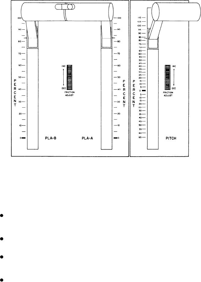
Figure 5-21.--PLA (throttle) and PITCH control levers.
MALFUNCTION Section
PLA AND PITCH CONTROL LEVERS
This section has four alarm indicators
Figure 5-21 shows the PLA (throttle) and
which are normally not illuminated. The alarm
PITCH control levers which are electronically
indicators are as follows:
connected to the PLA of the GTM and to the
CRP electronic enclosure, respectively. The
throttle levers are graduated in percentage of PLA
POWER SUPPLY--It illuminates red to
from 0 to 100 percent for each PLA. The pitch
indicate a summary fault condition at the
lever is graduated in percentage of pitch travel
PLCEE power supply.
from 0 to 110 percent (ahead) and from 0 to 65
percent (astern).
CONSOLE--It illuminates red to indicate
a summary fault condition at the PLCC.
SUMMARY
S/CE--It illuminates red to indicate a
summary fault condition at the PAMISE
In this chapter, we have presented informa-
signal conditioning enclosure.
tion to familiarize you with the controls and
indicators located on the consoles of the DD- and
S/CE EMER POWER ON--It illuminates
CG-class ships. The main consoles of other classes
of gas turbine-powered ships will be described in
red to indicate the signal conditioning
enclosure is using UPS emergency power.
later chapters of this TRAMAN. Do not attempt
5-47