
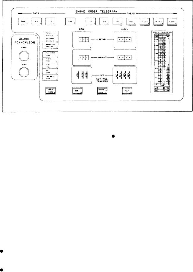
Figure 5-19.--EOT panel.
Investigate the alarmed condition follow-
Under the heading START/STOP MODE is
ing EOCC.
the two-position, rotary select switch labeled
MANUAL INITIATE and MANUAL CON-
ENGINE ORDER TELEGRAPH Section
TROL. This switch allows you to select the
starting and stopping mode.
When the SCC does not have throttle control,
the OOD must inform the station in control of
EOT PANEL
speed requirements. This is done through the
The EOT panel (fig. 5-19) is divided into two
EOT. The EOT is a communications system. It
sections labeled ALARM ACKNOWLEDGE and
transmits propulsion command information
ENGINE ORDER TELEGRAPH.
between the station in command (SCC) and the
station in control of the throttles (PLCC or the
ALARM ACKNOWLEDGE Section
PACC).
The EOT section has two major subsections,
This section has two push buttons (three on
the standard order push-button/status indicators
the CG console). They are the main interface
and the digitized EOT.
between you and the control console. Each time
The standard order push-button indicator
an alarm is activated, an audible alarm sounds.
section has 13 push buttons. Under the heading
Amber (potential danger) alarms sound a horn
BACK, three of the push buttons are labeled
and red (danger) alarms sound a siren. When any
FULL, 2/3, and 1/3. The next push button is
alarm activates, the recommended procedures to
labeled STOP. Under the heading AHEAD are
follow are listed as follows:
seven push buttons labeled 1/3, 2/3, STD, FULL,
Identify the alarm condition. The alarm
FLANK 1, FLANK 2, and FLANK 3. The last
indicator will come on flashing, and the
two push buttons are at the bottom of the panel
audible alarm sounds.
under the digitized EOT. These push buttons are
labeled RPM ACK and PITCH ACK. These 13
Acknowledge the alarm. Depress the
push buttons provide for communication of
proper alarm acknowledge push button.
standard orders to the PLCC. Standard orders are
This action silences the audible and causes
initiated at the SCC by moving the ITC lever to
the alarm indicator to glow steadily.
5-44