
GTM A/B PANEL
console) for each engine, and 11 alarm indicators
for the air and MRG system. It also allows the
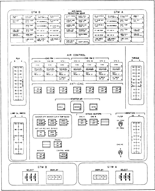
The GTM A/B panel (fig. 5-16) has the alarm
PLCC operator to monitor the air systems of the
indicators for the GTMs A and B, and the
engines in ENG RM 1, ENG RM 2, and GTG3.
controls and indicators for the various air systems.
This monitoring ability consists of three alarm
This panel is divided into-three sections. The first
indicators per engine and an alarm indicator for
section has 22 alarm indicators (23 on the CG
the HP air system of both engine rooms and
Figure 5-16.--GTM A/B panel.
5-40