
GTG3. This section of the GTM A/B panel also
parameter. The DDI displays this value in the
has 4 dual-indicating meters, 20 push-button
display windows. To use the DDI system, you
control indicators (21 on the CG console), and
determine the address for the required
2 toggle switches. Ail of these alarm indicators,
parameter,
push-button control indicators, dual-indicating
meters, and toggle switches have been previously
dial the address in the SELECT thumb-
described on the PACC.
wheels, and
The last two sections of this panel are the
observe the value of the parameter in the
DDIs. They are a mirror image of each other. The
display window.
DDI system is an operator information system.
The system is used to verify parameters, check the
In the DDI system, the values are continually
system's operation, and troubleshoot system
updated at the rate of four times a second.
malfunctions. Any parameter monitored can be
GTM A PANEL
displayed at any DDI location. The DDI system
uses a three-digit address to probe the memory
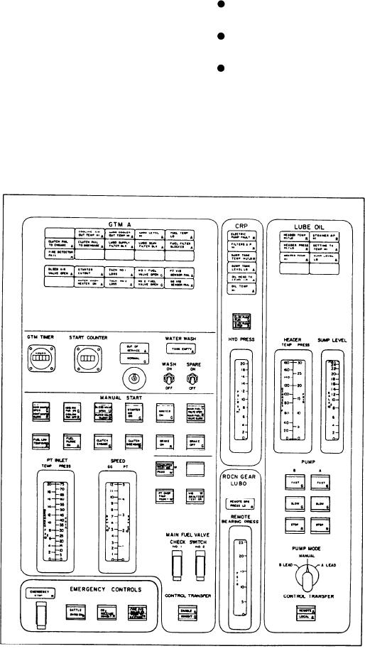
The GTM A panel (fig. 5-17) has the controls
of the computer and find the value of the
and status indicators for the GTM A and the
Figure 5-17.--GTM A panel.
5-41