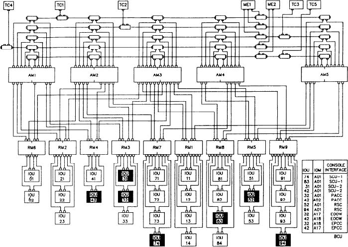
Figure 9-37.--DDG-51 DMS configuration.
perform the primary control functions associated
from the consoles. (See fig. 9-37.) The DMS
with starting message transfers when requested by
functionally connects the MCS equipment
the IOUs and responding to message transfer
together by data message transfers. This reduces
requests. The RMs also perform primary control
the number of cables that would otherwise be
functions associated with formatting messages for
required to achieve the same compatibility.
transmission and processing messages received
from other RMs or AMs. The IOUs interface with
DMS CONFIGURATION
user devices and the local RMs to provide user-
to-user communication paths. The IOU converts
Figure 9-37 shows the DDG-51 class DMS
the input user signals to the DMS signal format
configuration. The configuration shown has 29
and converts the digital data from the DMS to
IOUs, 9 remote multiplexers (RMs), 5 area
signals that are compatible with interfacing user
multiplexers (AMs), 5 traffic controllers (TCs),
device.
and 1 maintenance group (MG) contained in two
enclosures. The IOUs that interface with the MCS
DMS TO MCS COMMUNICATIONS
are shaded in figure 9-37.
The TCs operate independently of each other
Figure 9-38 is a block diagram of the devices
to provide orderly control of access to the primary
on the DMS bus that communicate with the MCS
busses. The AMs provide the interface for the
equipment. There are three categories of
groups of RMs so channel access offers from the
communications used with MCS, each with its
TCs are matched with the service requests from
own protocol. They are computer-to-computer
the RMs. The AMs issue service offers to the RMs
(smart-to-smart), computer-to-non-computer
so they can start message transfer. The RMs
9-58

