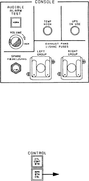
RIGHT GROUP. These fuses protect the exhaust
display keyboard. Accessible from the rear
fan circuits.
of the Al section are a power supply for
the plasma display and a tone generator
assembly with a speaker and a buzzer. The
front of the Al section has the mounting
for the plasma display, the AN/UYK-44 main-
tenance panel, two power supplies, a battery
charger, and a power/fuse panel. The A2
section has two battery assemblies, a transformer,
the AN/UYK-44 SEMs, and a bubble memory.
The front panels of the console are hinged
at the top so the panels can be raised to
reach the plasma display assemblies and the
other panel-mounted components.
The RSC provides centralized control of
the damage control equipment and serves as
the primary control station when the DCC
is not available. The RSC is a backup console
for the DCC and automatically switches the
primary damage control location between the
DCC and the RSC when certain failures are
Control Section
identified in the DCC. The RSC is located in
repair station 2.
This section contains two control push buttons
used to transfer damage control functions between
the DCC and the RSC. The first push button is
VERTICAL PANEL
labeled CTL CONT STA. It illuminates to show
the DCC has control of the firemain valves and
fire pumps. The second push button, labeled RPR
The vertical panel of the RSC consists of a
STA CSL, illuminates to show the RSC has
console section, a control section, a plasma
control of the firemain valves and fire pumps.
display unit, and the firemain panel.
Console Section
The first section of the RSC, labeled
CONSOLE, is located at the upper left of
the console. It contains a push-button indicator,
a rotary potentiometer, two indicator LEDs,
Plasma Display Section
and three fuse holders. The push button,
under the heading AUDIBLE ALARM TEST,
Located toward the center of the vertical panel
is labeled HORN. When depressed, this push
is a plasma display unit. All plasma display units
button sounds the horn. The rotary poten-
in the MCS are identical. A detailed description
tiometer, labeled VOLUME, adjusts the volume
of the plasma display was presented in chapter 7.
of the horn. The first LED is labeled TEMP
HIGH. It illuminates yellow to indicate the
temperature of the console has exceeded the
Firemain Panel
preset limit. The second LED, labeled UPS
IN USE, illuminates red to indicate the RSC
The firemain panel has a complete mimic of
is on UPS. The first fuse holder is labeled
the major piping of the firemain. (Refer to
SPARE F03B125VAS. It houses a spare fuse
fig. 9-34.) This panel is similar to the firemain
for the console. The next two fuse holders
panel on the DCC. Only the fire pumps can be
are under the heading EXHAUST FANS 115VAC
controlled and monitored from this panel.
FUSES. They are labeled LEFT GROUP and
9-54

