
and BUZZER. When depressed, these push
in the MCS are identical. A detailed description
buttons sound the horn and buzzer. The rotary
of the plasma display was presented in chapter
potentiometer, labeled VOLUME, adjusts the
7 of this TRAMAN.
volume of the horn and- buzzer. The first LED
is labeled TEMP HIGH. It illuminates yellow to
Firemain Panel
indicate the temperature of the console has
exceeded the preset limit. The second LED,
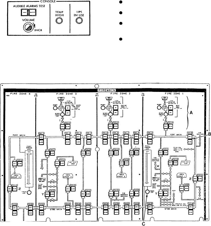
The firemain panel (fig. 9-31) has a complete
labeled UPS IN USE, illuminates red to indicate
mimic of the major piping of the firemain. The
the DCC is on UPS.
panel is divided into the following four fire zones:
FIRE ZONE 1 - Frame 0 to frame 126,
FIRE ZONE 2 - Frame 126 to frame 254,
FIRE ZONE 3 - Frame 254 to frame 370,
and
FIRE ZONE 4 - Frame 370 to frame 466.
Plasma Display Section
The firemain panel provides controls to
operate fire pumps No. 1, No. 3, and No. 5, the
Located toward the center of the vertical panel
firemain valves, and the washdown countermeasure
are two plasma displays. All plasma display units
valves. This panel also provides indicators to show
Figure 9-31.--Firemain panel.
9-51