
the position of the firemain valves, the status of
SLOPING PANEL
fire pumps No. 1, No. 3, and No. 5, and the
pressure of the port and starboard firemain
The sloping panel of the DCC contains the
risers.
controls and indicators for WDCM control, the
The DCC firemain panel displays the four fire
alarm acknowledge push button, the lamp test
zones. During the discussion of this panel, only
push button, and the fire pump panel.
FIRE ZONE 1 will be described. The other fire
zones are similar. Their differences will be pointed
out during the discussion.
Washdown Countermeasure
The first section of the FIREMAIN panel
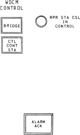
Control Section
monitors and controls three fire pumps and their
associated discharge valves. It contains four push-
This section is used to select which station has
button indicators and two LEDs. There are three
control of the WDCM valves. This section
identical sets of these indicators and controls on
contains two control push buttons under the
this panel, one for each fire pump (A). The first
heading WDCM CONTROL. The first control
LED indicator on the firemain panel is labeled
push button is labeled BRIDGE. It transfers
READY. It illuminates green to indicate the fire
control of the WDCM group 1 through group
pump is aligned for operation. A fire pump is
4 valves to the bridge control unit (BCU). It
ready for operation when its motor controller is
illuminates green to show the BCU has control
in remote, and its discharge valve and its sea
of the valves. The second control push button,
suction valve are fully open. The first control push
labeled CTL CONT STA, transfers control of the
button is labeled ON. When depressed, this push
WDCM group 1 through group 4 valves to the
DCC. It illuminates orange to show the DCC has
button starts the fire pump and illuminates green
control of the valves. The LED in this section is
to show the fire pump is running. The second
labeled RPR STA CSL IN CONTROL. It
control push button is labeled OFF. When
illuminates yellow to indicate the RSC has
depressed, this push button stops the fire pump
and illuminates white to show the fire pump is
control of the firemain valves, the fire pumps, and
the WDCM valves.
stopped. The second LED indicator, labeled
DISCH PRESS LOW, illuminates yellow to
indicate the fire pump discharge pressure is below
the preset limit. The third control push button is
labeled OPEN. When depressed, it opens the fire
pump discharge valve and illuminates green to
indicate the valve is open. The fourth control push
button is labeled CLOSE. When depressed, it
closes the fire pump discharge valve and
illuminates red to indicate the valve is closed.
Located below the fire pump controls are two
control push buttons labeled OPEN and CLOSE
(B). There are 40 identical sets of these push
buttons on the firemain panel. These push
buttons control the various firemain valves of the
Alarm Acknowledge
system and function the same as the fire pump
discharge valves. Located at the center of FIRE
The alarm acknowledge push button is labeled
ZONE 1 is a vertical reading meter labeled STBD
ALARM ACK. Depressing the ALARM ACK
push button silences the audible alarm and causes
PRESS (C). This meter continuously monitors the
pressure of the starboard firemain loop. An
the flashing indicator to illuminate steadily. The
identical meter, labeled PORT PRESS, is used to
indicator extinguishes when the alarm condition
clears.
monitor the port firemain loop. The meter for the
port loop is located at the center of FIRE ZONE
4. Associated with each vertical reading meter is
an LED labeled PRESS LOW. It is located at the
bottom of the firemain pressure meters. This LED
illuminates yellow to indicate a low firemain
pressure in the firemain loop.
9-52