
holders. The last fuse holder on this panel is
switches, 12 fuse holders, and 3 test points. The
power control panel is located on left side of the
labeled PLASMA. It holds the 5-amp fuse that
sloping panel.
protects the plasma display circuits. Located
The first rotary snap switch is labeled 115VAC
below the fuse holder section are three test points
MAIN/155 VDC BAT (A). The positions of the
(D). The first test point on the power control panel
switch are labeled OFF and ON/AUTO. In the
is labeled RTN. This is the return test point used
OFF position, no power is applied to the RSC.
with the self-test relay test points. The next two
In the ON/AUTO position, 115 volts ac is applied
test points are located under the heading SELF
TEST RELAYS. These test points provide for
to the RSC. This switch position also enables the
testing the self-test relays.
UPS circuitry. In the event normal power is lost,
the 155-volts dc UPS is supplied to the RSC. The
second rotary snap switch is labeled HEATER
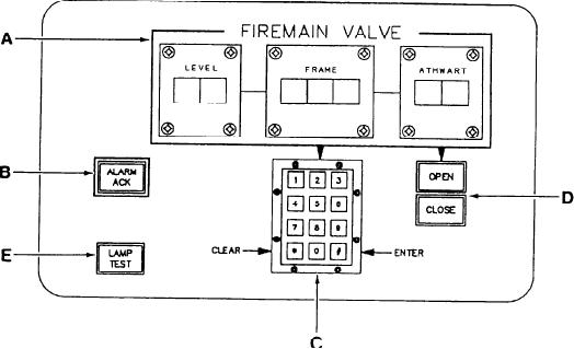
Firemain Valve Panel
(B). The positions of the switch are labeled ON
The firemain valve panel, shown in figure
and OFF. This switch controls the power to the
9-36, contains a digital indicator, four push-
console heater.
The right-hand side of the POWER CONTROL
button indicators, and a numerical keypad. The
PANEL is occupied by 12 fuse holders (C). The
firemain valves can be opened or closed from the
first two fuse holders, labeled HEATER and
RSC using the controls on the firemain valve
panel. The seven-digit valve number is addressed
HEATER RELAY, are the dual-cartridge type.
using the keypad, and the selected valve is
They hold the 5-amp fuses that serve to protect
displayed on the digital indicator. Once selected,
the heater and the heater relay circuits. The three
fuse holders, located under the heading FANS,
the appropriate push button is used to open or
are single-cartridge, twist-type fuse holders. They
close the valve.
The digital indicator (A) consists of three sec-
hold the 5-amp fuses that protect the fans of the
tions labeled LEVEL, FRAME, and ATHWART.
AN/UYK-44 computer, the transformer, and the
input/output multiplexer. The fuse holder, labeled
This indicator displays the seven-digit valve
AUDIBLE ALARM, holds the 5-amp fuse that
number of the selected valve to be controlled.
protects the audible alarm circuit. The three fuse
ALARM ACKNOWLEDGE.--The alarm
holders, under the heading 1 AMP, contain a
acknowledge push button (B) is labeled ALARM
spare 1-amp fuse, a 1-amp fuse for the self-test
ACK. Depressing the ALARM ACK push button
circuit, and a 1-amp fuse for the indicating switch
circuit. Next, there are two spare 5-amp fuse
silences the audible alarm and causes the flashing
Figure 9-36.--Firemain valve panel.
9-56