
Lamp Test
The next push button, located at the lower
center of the sloping panel, is labeled LAMP
TEST. Depressing this push button illuminates all
the lights on the console. The operator uses this
push button to determine which light bulbs
need replacing. Releasing the LAMP TEST push
button completes the test and extinguishes the
lamps.
Fire Pump Panel
The fire pump panel (fig. 9-32) is located
directly below the firemain panel. It contains the
controls and indicators for fire pumps No. 2, No.
4, and No. 6. This panel is also divided into four
fire zones. The controls and indicators on this
panel function identically to those discussed on
the firemain panel.
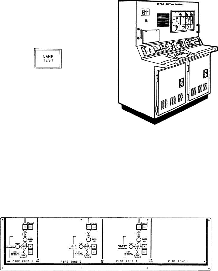
Figure 9-33.--Repair station console.
Plasma Display Keyboard
The final section of the DCC contains the
mounted in the enclosure through front and
plasma display keyboard. All plasma display
rear hinged access doors. Figure 9-33 is an
keyboards in the MCS are identical. A detailed
overall view of the console. The following
description of the plasma display keyboard was
paragraphs provide a physical description of
presented in chapter 7.
the RSC.
The RSC is a single structural enclosure
REPAIR STATION CONSOLE
with two sections designated as A1 and A2.
The front console has vertical and sloping
The RSC on the DDG-51 class ship is a two-
panels for mounting controls and displays
bay console with access to the components
and a work surface that supports a plasma
Figure 9-32.--Fire pump panel.
9-53