
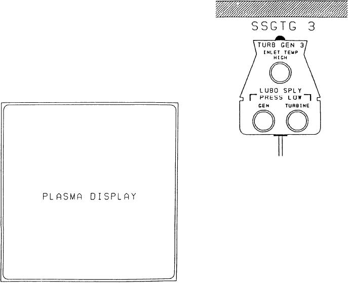
indicator, TURBINE, is for the LO pressure on
PLASMA DISPLAY Section
the GTE. It indicates the pressure on the GTE is
below the preset limit.
This section is an alphanumeric display
device. The plasma display provides the EPCC
operator with machinery status and alarm
information required to control and monitor
the electrical equipment. The plasma display
can be operated in two different modes,
status/alarm or summary group status. The
bottom portion of the display is used for
DDI display in both modes. The modes are
controlled by the plasma keyboard. The plasma
display works the same as the other plasma
displays described in chapter 7.
METERS.--The meters from top to bottom
are POWER, CURRENT, VOLTAGE, and FRE-
QUENCY. The power, current, and frequency
meters are 270-degree LED meters. The voltage
meter is also a 270-degree LED meter, but it
contains a three-digit LED display on the meter.
The meters are black in color and the parameter
area illuminates red in color. Red area increases
around the 270-degree arch as the parameter
increases.
REGULATOR MODE.--The REGULATOR
MODE selector switch/indicators are located to
the right of the VOLTAGE meter. The voltage
regulator mode switch/indicators are DIFF,
POWER GENERATION AND
DROOP, and MANUAL. The mode that is
DISTRIBUTION Section
selected will have its respective indicator illumi-
nated. The rotary switch, below the switch/
This section is divided into three identical
indicators, is used to RAISE or LOWER the
sections, one for each SSGTG. The sections are
voltage of the generator. It is spring loaded to the
labeled from left to right SSGTG 3, SSGTG2, and
center position.
SSGTG1. We will discuss the No. 3 SSGTG
section. The top indicator is labeled TURB
GOVERNOR MODE.--The GOVERNOR
GEN 3 INLET TEMP HIGH. It indicates the
MODE selector switch/indicators are located
temperature of the air at the inlet exceeds the
to the right of the FREQUENCY meter. The
preset limit. The next two indicators are labeled
governor mode switch/indicators are ISO and
LUBO SPLY PRESS LOW. The left indicator is
DROOP. The mode that is selected will have its
GEN. This indicator will illuminate when the LO
respective indicator illuminated. The rotary switch
is used to LOWER or RAISE the frequency of
system is below the preset limit. The right
8-48