
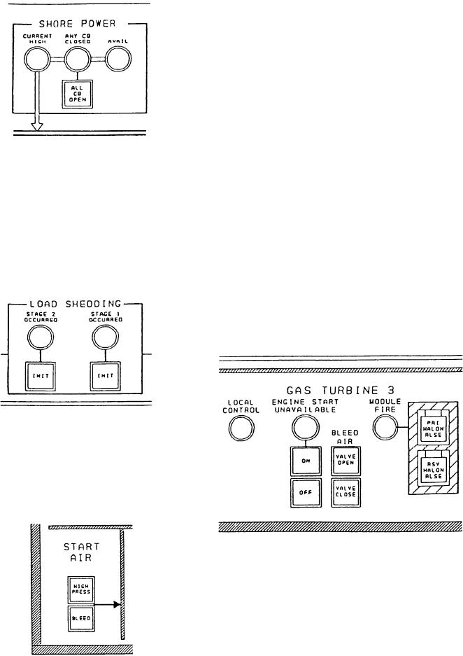
GAS TURBINE Section
circuit breakers are open. Depressing this switch
causes all shore power CBs to open.
This section is located across the lower
portion of the A-2 panel. It has three identical
sections, one for each SSGTG. The left indicator
is for LOCAL CONTROL. It indicates the
control of the SSGTG is not available from the
EPCC. The middle indicator is ENGINE START
UNAVAILABLE. It indicates the SSGTG is not
available to start. The switch/indicator under this
indicator is ON. It indicates the GTE is running
or in start sequence. The push button is used to
initiate a GTE start sequence. The bottom
switch/indicator is OFF. It indicates the GTE is
secured or in a stop sequence. The two switch/
indicators under the BLEED AIR heading are
LOAD SHEDDING Section
labeled VALVE OPEN and VALVE CLOSED.
This section contains two indicators and two
These switch/indicators function like the GB
switch/indicators. The left side of the section is
control switch/indicators. The last indicator in
for STAGE 2. The right side is for STAGE 1.
this section is MODULE FIRE. It indicates a fire
Each side has an indicator and a switch/indicator.
has been detected in the SSGTG gas turbine
The indicator labeled OCCURRED will illuminate
enclosure. The last two switch/indicators are
when load shedding has occurred in its respective
guarded push-button switch/indicators. The top
stage. When depressed, the switch/indicator
one is for PRI HALON RLSE. It is used to
labeled INIT will illuminate and will initiate its
activate the primary Halon release. It will
stage of load shedding.
illuminate when Halon has been released from any
location. The bottom switch/indicator is for RSV
HALON RLSE. It functions the same as the
primary switch/indicator.
START AIR Section
This section is located on the lower portion
of the A-2 panel. It has two switch/indicators.
The upper switch/indicator is for HIGH PRESS
air starting of the SSGTG. The lower switch/
indicator is for BLEED air starting of the SSGTG.
Synchronization Section
This section is located on the right side of the
panel. It contains a switch/indicator and a rotary
switch. The switch/indicator, SYNC MON BY-
PASS, is used to bypass the synchronizing
monitor in the SWBD. The rotary switch is a ten-
position switch. It is used to select the circuit
8-52