
spring-loaded, two-position toggle switch. The
distribution. Consult your ship's DDI index for
the addresses of these printouts.
calendar information is displayed in the light
emitting diode (LED) windows under the headings
DAY, HOUR, and SEC. The Julian date is
continuously displayed in the LED windows under
the heading DAY.
NOTE
Julian dates are numerically sequential
days of the year. For example, January 1
is day 001; January 2 is day 002; December
31 is day 365, except in a leap year when
it is day 366.
Under the headings HOUR and SEC, the
GMT clock displays the time of day in hours and
seconds in the LED windows in the 24-hour clock
MALFUNCTION SECTION.--The MAL-
FUNCTION section (C) has ten alarm indicators,
format. This clock allows logging to be consistent
an alarm/status test switch, and an alarm
from time zone to time zone without the operators
having to note time changes. The rotary switch
acknowledge push button. The MALFUNCTION
under the heading SET FUNCTION has three
section on the CG also has a alarm volume
positions: DAY, HOUR, and SEC. The operator
control knob. The alarm indicators illuminate
uses this switch to select a change in the Julian
either red or amber to alert the operator when
date, the hour, or the seconds shown in the LED
malfunctions occur within the PAMISE system.
windows. The thumbwheels labeled SET VALUE
The first alarm indicator, labeled ICC-S/CE 1,
illuminates red to indicate a fault in the
work in conjunction with the spring-loaded
information center console (ICC) No. 1 or in
toggle switch labeled SET. The operator uses the
the S/CE No. 1. The second alarm indicator,
thumbwheels to dial up the desired data to be
labeled ICC NO. 2, illuminates red to indicate
shown in the LED windows and raises the toggle
a fault in the ICC No. 2. The third alarm
switch to the SET position to load the data into
indicator, labeled S/CE NO. 2, illuminates
the computer.
red when a fault in the S/CE No. 2 occurs.
The fourth alarm indicator, labeled S/CE
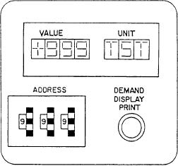
DEMAND DISPLAY SECTION.--The DE-
NO. 3, illuminates red when a fault in the S/CE
MAND DISPLAY section (B) contains a demand
No. 3 occurs. The fifth alarm indicator is
display indicator (DDI), a set of three thumb-
labeled POWER SUPPLY. It illuminates red to
wheels, and a push-button switch. The DDI
indicate a fault in one of the engineering control
display allows operators to display a selected
and surveillance system (ECSS) power supplies.
parameter by setting up the address on the
The sixth alarm indicator is labeled CLOCK NOT
thumbwheels. The display on the CG-class ships
SET. It illuminates amber when the calender
will also show the unit of measurement of the
clock has not reset after a loss of ECU power.
selected address. You can select and display
The seventh alarm indicator, labeled BELL
any plant parameter as long as it has a DDI
LOGGER, illuminates amber when the bell
address.
logger is not on line or when a fault occurs.
The eighth alarm indicator, labeled DATA
A PRINT push button (DEMAND DISPLAY
PRINT on the CG) is also associated with
LOGGER, illuminates amber when the data
logger is not on line or when a fault occurs. The
the DDI. When depressed, this push button
ninth alarm indicator, labeled BELL LOGGER
causes the parameter selected by the address
PAPER LOW, illuminates amber to indicate that
to be printed on the data log. The DDI index
there are about ten blank sheets of paper
also has special addresses that allow group
remaining in the bell logger. The last alarm
printouts to be printed on the data log. Print-
indicator, labeled DATA LOGGER PAPER
outs of groups include areas such as power
LOW, illuminates amber to indicate that there are
train, fuel oil, lube oil, GTM, GTG, and 60-Hz
9-3