
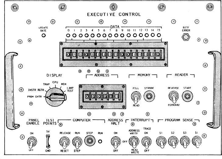
Figure 9-2.--ECU test panel.
indicate the S/CE 2 is on normal SS power. The
CAUTION
fourth indicator, labeled S/CE NO. 2, illuminates
red to indicate the S/CE No. 2 is on UPS. The
The potential for causing malfunctions to
fifth indicator, labeled S/CE 3, illuminates green
the entire ECSS network is very high if the
to indicate the S/CE 3 is on normal SS power.
equipment is operated by inexperienced
The sixth indicator, labeled S/CE NO: 3,
maintenance personnel. A technician must
illuminates red to indicate the S/CE No. 3 is on
have a thorough understanding of the
UPS.
serial data networks, binary logic, and
digital equipment before operating the
ECU test panel. The operation of the ECU
ECU Test Panel
test panel is beyond the scope of this
training manual (TRAMAN) and will not
The ECU test panel (fig. 9-2) is located inside
be covered.
the CISE enclosure at the back of the CISE
cabinet. The test panel is the primary interface
SIGNAL CONDITIONING EQUIPMENT
to the ECU. The computer program (operated
only by experienced GSEs) is loaded, run, and
Signal conditioning is done by the PAMISE
at the S/CEs No. 1, No. 2, and No. 3. The
maintained through this panel. The tape reader
purpose of these S/CEs is to convert all the
panel (not shown) consists of a punched tape
sensory inputs into a common electrical range of
reader, two reels, and a two-position toggle
switch. The tape reader reads the ECSS program
0 to 10 volts dc. This conversion makes the
from a prepunched tape and loads the informa-
inputs compatible with the rest of the ECSS. The
tion into the memory core of the ECU.
S/CE No. 1 monitors the electric plant. The
9-5