
the FO fill and transfer system. The JP-5 control
both the FO fill and transfer system and the
JP-5 system. T h e front of the FSCC is
panel (A5) contains the operator controls and
indicators for the JP-5 fill, transfer, and service
divided into two operator panels; the upper
systems.
panel is the FO fill and transfer control panel, and
the lower panel is the JP-5 control panel. (See also
The indicators and controls on the front panels
fig. 9-7.) These panels have mimics of the
associated system, vertical reading meters to
of the FSCC will be discussed first, from left to
right and top to bottom; followed by the back
display system parameters and tank levels,
panels in the same left-to-right, top-to-bottom
indicator lights to display system status, and
push buttons to remotely control motor-operated
fashion. Refer to figure 9-7.
equipment.
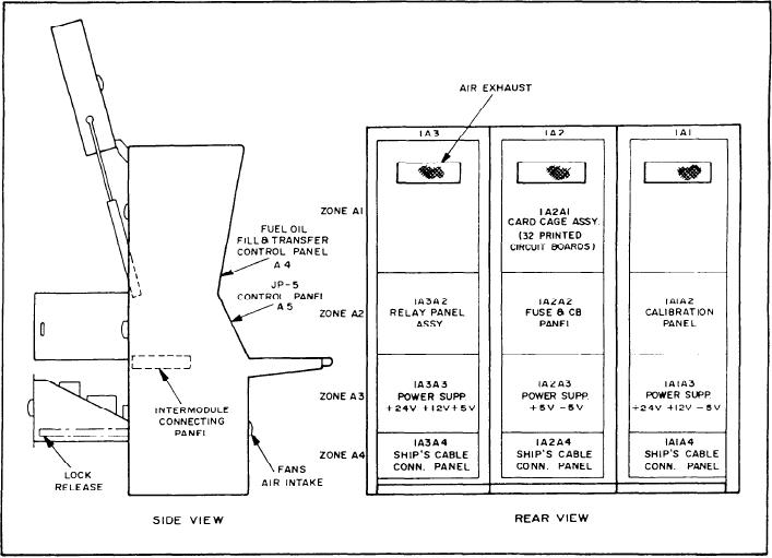
The FSCC has three main cabinet assemblies
Fuel Oil Fill and
(A1, A2, A3), the FO fill and transfer control
Transfer Control Panel
panel (A4), and the JP-5 control panel (AS).
Figure 9-7 shows the console outline and
The FO fill and transfer control panel will be
discussed in two sections. (See fig. 9-8.) The upper
component location. The three main cabinet
assemblies contain the power supplies, electronic
section of the panel will be referred to as the fuel
hardware, and internal wiring of the FSCC.
oil fill section; the lower section as the fuel
oil transfer section. This system is shown in full
The FO fill and transfer control panel (A4)
in figure 9-8 and in greater detail in figures 9-9
has the operator controls and indicators for
Figure 9-7.--Fuel system control console--component location.
9-10