
monitoring of up to 16 operator-selected param-
to receive data. The second switch, a two-position
eters and automatic printout if a parameter's
toggle switch labeled ON/OFF, turns the line
value changes by more than a preset threshold
printer on and off. The last switch is a two-
position, spring-loaded toggle switch labeled
(percentage).
TEST. This switch tests the printer operation by
DEMAND PRINT LOGGING.--The demand
printing out a test pattern when the operator raises
print logging function provides the operator with
the switch to the TEST position.
a printout of an individual item or a group of
items. To accomplish this, the operator dials up
the address for the information desired to be
FUEL SYSTEM
printed and depresses the print push button.
CONTROL EQUIPMENT
If either of the line printers should fail to
The fuel system control equipment is not
operate properly, the remaining operable printer
connected to any components of the ECSS. It is,
automatically assumes all logging duties. In this
however, an important electronic control console
event, the priorities for logging time, in order of
on the DD-963, DD-993, and CG-47 class ships;
highest to lowest, are as follows:
therefore, it is discussed in this chapter as is the
1. Bell logging
damage control console.
2. Alarm logging
The major components of this system include
3. Status change logging
the fuel system control console (FSCC), two fuel
4. Trend logging
oil (FO) transfer local panels, and the JP-5 local
5. Demand and data logging
control panel. These consoles and panels are an
integrated information and control system. They
The line printer control panel consists of two
provide operator control and monitoring from
indicator lights and three toggle switches. The first
local and remote locations. In most cases, infor-
indicator light, labeled POWER, illuminates green
mation generated by one unit of its system is
to indicate electrical power is applied to the
shared by one or more of the other units.
printer. The first switch is a two-position, spring-
loaded toggle switch labeled FORM FEED. It
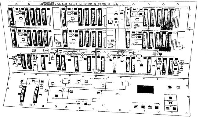
FUEL SYSTEM CONTROL CONSOLE
advances the paper in the printer to the next page.
An FSCC is shown in figure 9-6. This console
The second indicator light, labeled ON-LINE,
provides centralized monitoring and control of
illuminates green to indicate the printer is ready
Figure 9-6.--Fuel system control console.
9-9