
about ten blank sheets of paper remaining in the
to preset the amount of variance of the parameter
data logger.
before printout occurs. This range is set between
1 to 10 percent of full scale. The ADDRESS
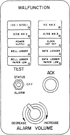
When any of these malfunctions occur, the
thumbwheels allow the operator to select the
appropriate alarm flashes and a buzzer sounds.
parameter to be trend logged.
Depressing the ALARM ACKNOWLEDGE push
button (labeled ACK on the CG) will silence the
The three push buttons labeled LOAD,
buzzer and cause the indicator to illuminate
steadily. The alarm indicator extinguishes when
INHIBIT, and PRINT are used when the operator
is setting, securing, and reviewing the trend
the malfunction clears. On the CG, the volume
logging. The two-position switch, labeled ON and
of the buzzer can be adjusted by rotating the
OFF, is used to turn on or turn off trend logging
ALARM VOLUME control knob (this feature
functions. The three push buttons are used to
does not exist on the DD). The three-position
program the digital computer for trend logging.
toggle switch allows the operator to test the alarm
and status indicators. The three positions of the
After placing the toggle switch to the ON
position and setting all the thumbwheels, the
switch are labeled STATUS, OFF, and ALARM.
operator depresses the LOAD push button to
program the selected parameter into trend logging.
The PRINT push button signals the data logger
to print out all active trend logging parameters.
The INHIBIT push button is used to stop the
trend logging of a selected parameter. Trend
logging is useful for monitoring recently repaired
equipment to establish trend data. It is also useful
for logging of data during full power and
economy trials.
PRINT INTERVAL SECTION.--The PRINT
INTERVAL section (E) contains a two-position
switch labeled 1 HOUR and 4 HOUR. This switch
sets the interval when the data logger will
automatically print a complete plant printout.
ALARM STATUS REVIEW SECTION.--
The ALARM STATUS REVIEW section (F) con-
tains a push-button switch labeled PRINT. When
depressed, the switch commands the data logger
to print out all active alarms in the ECSS. This
function is useful to the engineering officer of the
watch (EOOW) when reviewing the active alarms
and out-of-limits parameters before relieving the
watch.
POWER SECTION.--The POWER section
TREND LOGGING SECTION.--The TREND
(G) consists of three status indicators, under the
LOGGING section (D) of the CISE (not
heading NORMAL, and three alarm indicators,
applicable on the CG) allows certain parameters
under the heading EMERGENCY. These six
to be printed onto the data log when a selected
indicators allow the operator to monitor the status
limit is exceeded. The TREND LOGGING section
of the power supplies in the PAMISE system. The
has three groups of thumbwheels, three push
first indicator, labeled CISE, illuminates green to
buttons, and a two-position toggle switch. The
indicate the CISE is on normal ship's service (SS)
three thumbwheel groups are labeled FUNC-
power. The second indicator, labeled CISE,
TION, THRESHOLD, and ADDRESS. The
illuminates red to indicate the CISE is on the
FUNCTION thumbwheels allow the operator to
uninterruptible power supply (UPS). The third
select 1 of 16 trend logging memory locations. The
indicator, labeled S/CE 2, illuminates green to
THRESHOLD thumbwheel allows the operator
9-4