
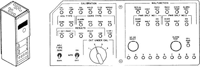
Figure 9-4.--S/CE No. 2 and S/CE No. 3 self-test panel.
calibration panel on or off or to set it for
indicators are labeled OVER TEMP, MALF, and
ON UPS. The first LED, labeled OVER TEMP,
automatic. In the OFF position the calibration
panel is disabled. The ON position allows the
illuminates red to indicate an overtemperature
operator to conduct adjustments and calibrations
condition in power supply No. 1. The second
of the various circuit cards. In the AUTO
LED, labeled MALF, illuminates to indicate a
position, the self-test panel allows for the
malfunction within power supply No. 1. The last
generation of the self-test signal that is distributed
LED, labeled ON UPS, illuminates red to indicate
to respective ECSS equipment. The four-position
the power supply is on UPS. The next three LED
rotary switch, labeled CKT UNDER CAL, allows
alarm indicators, under the heading PWR SPLY
the operator to select the circuit on the circuit card
NO. 2, are identical to the LEDs discussed for
to be tested.
power supply No. 1. The first push-button switch
located on the left side of the MALFUNCTION
MALFUNCTION Section
section is labeled NO GO RESET. The operator
Refer to section B in figure 9-3. The
uses this switch to clear the alarms on the CISE
MALFUNCTION section (B) consists of 13 LED
or respective S/CE. The other push-button switch,
status/alarm indicators, two push-button switches
located on the right side of the MALFUNCTION
and ten test jacks. This section provides the
section, is labeled SER CLK RESET (labeled
operator with a visual indication of a malfunc-
ALARM TEST on S/CEs No. 2 and No. 3). On
tion within the respective S/CE and the status of
S/CE No. 1, the operator uses this push button
that system. The first six LED alarm indicators
to reset the serial clock. On S/CEs No. 2 and No.
illuminate red to provide an indication of a
3, the operator uses this push button to conduct
malfunction in the S/CE (and the ECU for S/CE
tests of the S/CE alarms. The last LED indicator,
labeled CSL PWR ON, illuminates red to indicate
No. 1). The first LED, labeled SERIAL TRANS,
indicates a malfunction in serial transmission. The
that CISE console power is on. The 10 test jacks
second LED, labeled CONT, indicates a break in
along the bottom of the MALFUNCTION
continuity in the S/CE. The third LED, labeled
section allow the operator to read various data
RACK NO. 0 (RACK NO. 2 on S/CEs No. 2 and
test points within the S/CE.
No. 3), indicates a malfunction in the respective
BELL AND DATA LOGGERS
logic rack. The fourth LED, labeled RACK NO. 1
With all the equipment that must be monitored
(labeled RACK NO. 3 on S/CEs No. 2 and No. 3),
indicates a malfunction in the respective logic
and all the information that must be logged for
rack. The fifth LED, labeled OVER TEMP,
future reference, it would be nearly impossible for
indicates an overtemperature condition within the
a single operator to operate the console and write
in a log. For this reason, two line printers are
S/CE. The last LED in the first row, labeled ECU
designed to receive information from an ECU and
(labeled ALARM TEST on S/CEs No. 2 and
No. 3), indicates a malfunction in the ECU
log this information automatically. These line
(indicates an alarm test on S/CEs No. 2 and
printers, the bell logger and the data logger, are
identical in design and operation. The only
No. 3). The next three LED alarm indicators are
difference is in the information the printer is
under the heading PWR SPLY NO. 1. These
9-7