
Figure 9-5.--Line printer.
DATA LOGGING.--The data logging func-
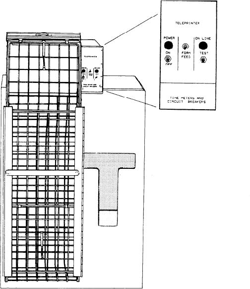
commanded to print. Figure 9-5 shows a detailed
tion provides a record of the values and/or status
view of one of the line printers.
of all parameters of interest, either automatically,
at selected time intervals, or upon operator
Bell Logger
demand.
The bell logger prints only bell signals and
ALARM LOGGING.--The alarm logging
replies to those signals. Bell signals include
function provides a permanent record of all
rpm commands, pitch commands, and station in
changes in alarm conditions as they occur, in-
control status. All other logging functions are
cluding both the alarm itself and its acknowledge-
done by the data logger.
ment or reset.
Data Logger
STATUS CHANGE LOGGING.--The status
change logging function records nonalarming
The data logger is responsible for all logging
changes in the discrete status of certain param-
functions not performed by the bell logger. These
eters, such as pump on/off or pump fast/slow.
functions include data logging, alarm logging,
TREND LOGGING.--The trend logging
status change logging, trend logging, and demand
function provides continuous and automatic
print logging.
9-8