
the generator. It is spring loaded to the center
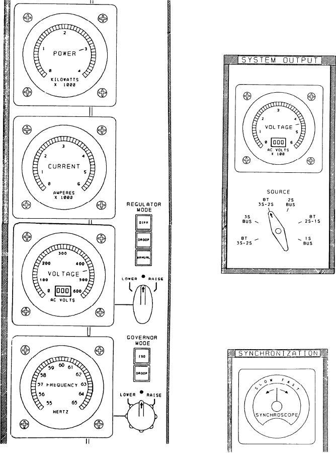
SYSTEM OUTPUT Section
position.
This section has a VOLTAGE meter and a
SOURCE switch. The VOLTAGE meter is the
same as the voltage meters on the power
generation and distribution section. The SOURCE
switch is used to select the input, a bus tie or a
bus, to the meter.
SYNCHRONIZATION Section
This section has a SYNCHROSCOPE meter
on this panel, and the selector switch is located
on the A-2 panel. The synchroscope functions the
same as the synchroscopes on the FFG console.
8-49