
end (15, 24), allows the assembly to work as a single
rotating group. The rotating group is supported by
journal bearings (3, 14) and seals (4, 13) on each end
of the shaft assembly. A thrust washer (23) and the
rotor (2) take up end thrust at the compressor end.
Study how this assembly works as we trace the
airflow.
Outside air is drawn into the compressor
through the inlet plenum (1). Here it is compressed in
two stages. The first-stage diffuser (6) guides the
discharged air from the first-stage impeller (5) into
the inlet of the second-stage impeller (21). The
second-stage diffuser (7) then guides the compressed
air into the turbine plenum (17), which provides
outlets for de-icing bleed air and other external uses.
From the turbine plenum, the compressed air flows
into the combustion liner assembly (11) of the
combustion chamber (9, 11). In the combustion
chamber, the compressed air is mixed with fuel
supplied by the fuel nozzles (10) and ignited by the
igniter plug (8). The resulting hot gases flow to the
first-, second-, and third-stage turbine wheel
assemblies (18, 19, 20). The spent gases are expelled
through the exhaust flange assembly or tailpipe (16).
Now that we have traced the airflow, let's look at
the SSPU in terms of its different systems, starting
with the electrical system.
ELECTRICAL SYSTEM
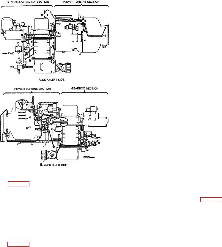
Figure 7-6.--SSPU left and right side views.
The SSPU electrical system automatically
actuates various electrical circuits in proper
sequence. These circuits control starting, acceleration
Figure 7-6 shows the design and construction of
and governed speed, fuel flow, and monitoring during
the SSPU as you would see it from the left side (view
SSPU operation. The major components of the
A) and right side (view B). The power section is
electrical system, as identified in figure 7-8, include
coupled to the reduction gear train by a splined
the following units:
torsion shaft. The shaft transmits power from the
SSPU to drive the driven components at a constant
Electric starter
speed. This gear train arrangement allows the
electrical starter to drive the power section and
Oil pressure switches
necessary equipment during the start cycle.
Ignition unit
To understand the design and operation of
the SSPU, let's take a closer look at the power
Monopoles
section. Figure 7-7 is a diagram of airflow in the
power section. As we describe the major
Speed switch
components, we will include numbers in
parentheses. Use these numbers to refer to the
Load and speed control
corresponding parts on the figure.
Thermocouples
In the compressor and turbine assembly, the
compressor impellers (5, 21) and turbine wheels
Electronic temperature control (ETC)
(18, 19, 20) are locked together by curved
couplings. A shaft assembly, consisting of a tie
Governor actuator
bolt through the center (22) with a nut on each