
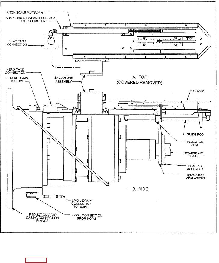
Figure 5-3.-Pitch scale platform showing temperature-compensated pitch indicating system.
compensated) surface and a primary means to sense
potentiometer and local pitch indicator, as shown in
views A and B of figure 5-3. This indicator is defined
information to the machinery control system (MCS).
as
temperature compensated because the indicator arm
Electronic Pitch Indicator System. In
is connected to the prairie air tube. (See view B.) The
prairie air tube is normally pressurized with air at a
addition to the temperature-compensated pitch
controlled temperature, and will have a fixed amount
indicator installed on the OD box of DDG-51 class
of thermal growth. Hence, the indicator arm is
ships, an electronic pitch position transducer is
provided with a thermally stable (temperature
installed behind a cover