
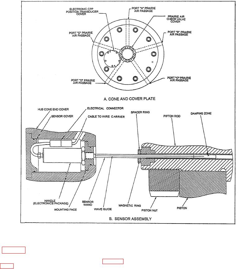
Figure 5-4.-Hub-mounted electronic pitch position transducer.
box. It contains the circuitry to provide a 10-kHz
plate on the propeller hub, as shown in view A of
excitation signal to, and receive a CPP position
figure 5-4. The electronic pitch indicator receives an
feedback signal from, the rotary transformer. The
input from a sensor assembly mounted inside the
cabinet also has two light emitting diode (LED)
propeller hub, as shown in detail in view B of figure
displays that show propeller pitch in both feet and
5-4. The sensor (wand) extends from the small
percent of design ahead pitch. The rotary transformer
electronics package (handle) located in the hub cone
contains both the transducer excitation and output
and cover into an axial hole drilled into the piston
coils. The rotating electronics rectifies the rotary
rod. The hole contains a magnetic ring that allows
transformer excitation to 24 V dc for powering the
the sensor to measure CPP position.
hub-mounted transducer and receives the transducer
output. The rotating electronics is attached to the
The electronic pitch indicator system also contains
prairie air tube extension at the end of the OD box. It
a stationary electronics cabinet, rotary transformer,
regulates
and rotating electronics cylinder. The stationary
electronics cabinet is mounted adjacent to the OD