WARNING
AFTER TEST FIRING, YOU MUST
NOT USE A METAL TOOL TO PUSH
THE HAMMER AND LOCK AS-
SEMBLY BACK FROM THE FIRING
WALL. TAKE EXTREME CARE TO
AVOID SCRATCHING OR ABRADING
THE POLISHED SURFACE OF THE
LOCK. THE PURPOSE OF THE LOCK
ASSEMBLY IS TO MATE WITH THE
ANEROID SEAR AND INITIATE FIR-
ING AT A PRESCRIBED ALTITUDE.
A ROUGH OR SCRATCHED LOCK-
ING ASSEMBLY MAY CAUSE A
HANGUP DURING THE UNLOCKING
FUNCTION.
NOTE: Ripcord release
assemblies with part number
711-07022-30 (10,000-foot)
must fire at 10,000 feet (plus
or minus 1,000 feet) pressure
altitude. Ripcord release as-
semblies with part number
711-07022-34 (14,000-foot)
must fire at 14,000 feet
(plus or minus 1,000 feet)
pressure altitude.
10. Three firing altitude checks must be made.
Any ripcord release that does not meet test
requirements on all three checks will be rejected.
Adjustments are not to be made.
11. Remove the dummy cartridge and inspect
it for an indentation caused by the hammer firing
pin striking the cartridge. This dent must be visible
to the QA performing the inspection.
ARMING AND ASSEMBLING THE
AUTOMATIC PARACHUTE RIPCORD
RELEASE
The following instructions are the same type
you will follow in the shop when arming and
assembling the Model 7000 ripcord release. When
you use the NAVAIR 13-1-6.2 manual and come
to a step that is followed by “(QA),” that step
must be inspected by a QA.
1. To arm the ripcord release that is installed
in a parachute, your first step is to insert the
arming cable housing through the holes in the
parachute container and ripcord release pocket.
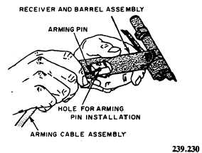
2. Next, feed the arming cable through the
arming cable housing. Depending on application,
the arming cable may be inserted at either side of
receiver and barrel assembly (fig. 2-11).
Figure 2-11.—Installing an arming cable.
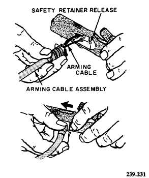
Figure 2-12.-Installing an arming cable housing.
3. With the ripcord release barrel in the open
position, install the arming pin into the ripcord
release. The pin must pass through the hole in the
side of the receiver, through the firing mechanism
lock, and out the opposite side of the receiver.
4. Next, you connect the arming cable housing
to the receiver and barrel assembly. Ensure the
safety retainer secures the housing to the receiver
(fig. 2-12). Be sure that you check the cartridge
service life at this time. You should not install a
cartridge that will expire prior to the next scheduled
repack of the assembly. Refer to NAVAIR
11-100-1 for the service/total life of cartridges.
2-7


